Substation Product Design Guid
This section provides you with operation suggestions of the substation design product V1.0 in Greenwich and related references. Read this section to get acquainted with the substation siting and design procedures.
Product Application Scope
The substation product V1.0 consists of two main functions: substation siting and substation design.
Substation siting is applicable in centralized and some distributed wind farms because only the economic and disruptive factors are considered in substation siting. Currently, only single substation siting (including preassembled substation and traditional substation) is supported.
Substation design is applicable for the newly added preassembled substations with the voltage level of 10kV, 35kV, 110kV, and 220kV. The feasibility study and initial design phases are supported. Currently, the expansion, renewal of substation and design of multiple substations are not supported.
Design References
- Requirement specifications of the substation product
- High-voltage and low-voltage preassembled substation GB17467
- Code for design of electric device and automatic relay protection device GB50062
- Code for design of 35kV - 110kV substations GB50059
- Code for design of fire protection in thermal power plant and substation GB 50229
- Technical regulations for design of 220kV - 750kV substations DLT5218
- Technical regulations for design of substation layout DLT5056
- Technical regulations for design of reactive compensation device in 35kV - 220kV substations DLT5242
- State grid general code for design of 110kV substations QGDW203
- Electric technical guide for 220kV - 500kV substations QCSG10011
- Eighteen measures against major power grid accidents
Substation Siting
In order to achieve the lowest overall cost of power line, road network, and route, the substation siting function offers the location recommendations of substations and ranking list of cost compositions.
Substation Location Area
The substation location area greatly impacts the efficiency of substation siting. To enhance the efficiency, it is suggested to minimize the siting area within the wind farm scope.

Map
The accuracy of map greatly impacts the result of substation siting. The known map sources are:
- Survey map
- Map from the Greenwich system
Use survey map preferentially. If no survey map is available for the project, use the map offered by Greenwich and adjust the contour interval as 5 m.

Parameter Setup
Basic Information
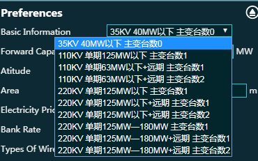
Select the scheme with substation capacity and voltage level according to the wind farm capacity. The different schemes selected might bring various impact to the cost and occupied area of substation.
The current-period or long-period capacity here refers to the current-period or long-period planned construction capacity of substation other than that of wind farm. The current-period or long-period planned construction capacity of substation refers to the main transformer capacity planned for the current-period or long-period construction.
Area

The substation occupied land area is recommended corresponding to the selected scheme.
The recommended area is the occupied land area within the preassembled substation wall. For traditional substations, expand the area in a proper proportion. If no domestic facilities, such as maintenance building or basketball court are to be constructed, add 10-20 m to the original length and width. If there is a plan to construct domestic facilities, such as maintenance building or basketball court, consult electric professionals for suggestions.
Siting Result Selection
After the siting calculation is completed, select the substation siting object. The result of substation siting is displayed within the siting scope. The five sites marked by red are the first five substation siting recommendations with most economic value.
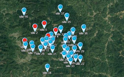
Double-click the substation siting object to view the economic result of substation siting.

Select the sites with the better economic value. The recommended sites should be verified in person because of the map error (without survey map), unclear geological condition (without geological exploration material), the hydrological and meteorological material that cannot be input. The issues to be verified are listed as follows:
- Substation location
- Located at the steep slope
- Located at the valley (This is the area with great precipitation where the rain might gather.)
- Distance to avoiding range (For substation location without definition of buffer area, it should be located next to the boundary of avoiding range.)
- Located in other unspecified avoiding range (such as lake, river, tomb, etc.)
- Transportation condition
For project in hilly area, the substation site might be at the hill top. The maintenance and operation factors should be taken into account. By substation siting, additionally select the sites close to the road on the hill and at the bottom of the hill for the final determination of site reconnaissance.
Considering the factors mentioned above, adjust the substation site within the 200 m scope around it. The adjustment within this scope would not bring out disruptive impact on the siting result.
Substation Design
Substation design is the calculation of material and engineering quantity of its construction according to the land form of its location and associated power line scheme.
Basic Information
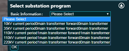
Select voltage level and number of main transformers for the substation according to the following suggestions:
Voltage level
Select 35 kV when wind farm capacity ≤ 40MW.
Select 110 kV when wind farm capacity ≤ 120MW.
Select 220 kV when wind farm capacity ≥ 120MW.
The voltage levels listed above are those commonly used in the configuration. The actual determination of voltage level should be based on consideration of accessible voltage level in the adjacent grid and the reply and suggestion from the ultimate access system.
Number of main transformers
If the entire wind farm is planned to be constructed in one construction, select one main transformer (For large-scale capacity (larger than 200 MW) wind farm, select no less than two main transformers and verify with electric professionals before your selection.)
If the entire wind farm is planned to be constructed by stages and the construction time of later stages is close to that of the first stage (within one year), select one main transformer (For large-scale capacity (larger than 200 MW) wind farm, select no less than two main transformers and verify with electric professionals before your election.)
If the entire wind farm is planned to be constructed by stages and the construction time gap between the first stage and later stages is long, select two main transformers.
Current-period and long-period capacity
Distinguish the wind farm current-period capacity and long-period capacity from substation’s current-period capacity and long-period capacity. The values you set here are the substation’s current-period and long-period capacity, that is, the main transformer capacity put into operation in current period and that in future period.
Scheme Selection
After you setting up the information above, the recommended substation design scheme is displayed. If no matched substation design scheme is available, preferentially select the scheme with the same voltage level or number of main transformers. With regard to the content of scheme adjustment, the solutions team is able to deal with the corresponding operations. Consult the professionals of each domain for other issues.

PBOM and Estimation
After you select the scheme, double-click the substation scheme object to view the corresponding PBOM. If you change your scheme selection, click the Generate button to generate new PBOM. If the scheme is not changed, do not click Generate. Or else, the manually modified PBOM parameters would be overwritten.
Electric I
Main transformer system

The main transformer capacity here should be in accordance with that defined in current-period capacity.
High-voltage XX gap

The wiring forms of ‘wire-transformer group’ and ‘single busbar’ are substitutes for each other. Single busbar wiring is consisted of outgoing circuit gap, PT gap, and main transformer ingoing circuit gap.
Output and measure switch cabinet

The switch station owns this device, and the booster station does not.
Section switch and disconnecter switch cabinet

This object exists only in the single busbar section switch wiring form (two main transformers). Connect section switch cabinet to Section I of busbar and disconnecter switch cabinet to Section II of busbar.
Reactive compensation system

It is configured based on 20% - 30% of the main transformer capacity. In common conditions, configure only SVG. In the following two situations, consider configure FC:
- When Reactive compensation capacity is too large and the SVG cost is too high (for example, the Reactive compensation capacity is larger than 25 Mvar).
- Access system requires specific filter performance, so configure FC with filter capacity.
Various cabins


Increase or decrease cabins for the specific project. The change of any cabin might lead to variation of electric general layout drawing. Make record of the changes of this kind and inform electric professionals to update the drawings.
Land acquisition area

In actual projects, the acquired land type and area should be determined by site land type, terrain, and gradient conditions. The value given in the scheme are referential. Verify with civil engineering professionals for final result.
Electric II
Measurement and control device
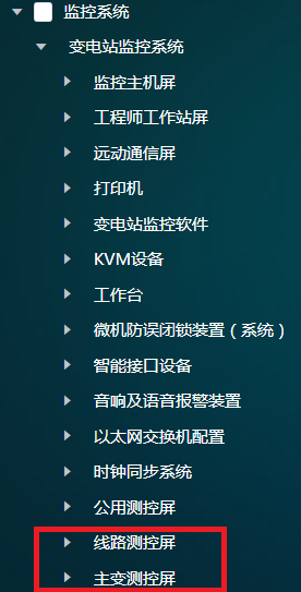
Configure the measurement and control screen according to main wiring gap type from the Electric I configuration.
Circuit measurement and control screen:
When high-voltage outgoing circuit gap minuses the quantity of enclosed-type assembled switch gear is n, multiply each material quantity of circuit measurement and control screen by n.
When high-voltage outgoing circuit gap minuses the quantity of open-type power distribution device switch gear is n, multiply each material quantity of circuit measurement and control screen by n.
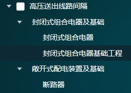
Enclosed type and open type are substitutes for each other and cannot coexist.
Main transformer measurement and control screen: When the number of main transformers is n, multiply each material quantity of main transformer measurement and control screen by n.

Protection device
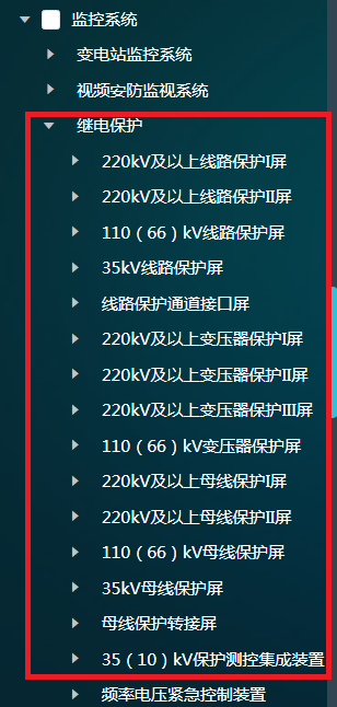
Circuit protection screen (including 220kV, 110kV, and 66kV):
When high-voltage outgoing circuit gap minuses the quantity of enclosed-type assembled switch gear is n, multiply each material quantity of circuit protection screen by n.
When high-voltage outgoing circuit gap minuses the quantity of open-type power distribution device switch gear is n, multiply each material quantity of circuit protection screen by n.
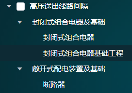
Enclosed type and open type are substitutes for each other and cannot coexist.
35kV circuit protection screen:
When the quantity of outgoing circuit and switch cabinet is n, multiply each material quantity of 35kV circuit protection screen by n.
No shield sets is needed and there is no material. This is the default manner in the model.
The two manners introduced above are substitutes for each other.

Transformer protection screen (including 220kV, 110kV, and 66kV):
When the number of main transformers is n, multiply each material quantity of transformer protection screen by n.
Busbar protection screen (including 220kV, 110kV, and 66kV):
Do not configure wire-transformer group wires.
By default, configure one set of single-busbar wire.
35/10kV integrated device for protection and measuring control
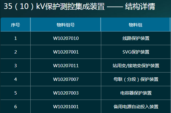
Circuit protection device is applied in the following two situations:
Only when it is taken as switching station, configure circuit optical fiber differential protection + circuit current protection device. In other situations, configure only circuit current protection device.
Circuit optical fiber differential protection (35kV/10kV): When it is taken as 35kV or 10kV switching station and the quantity of 35kV circuit protection screen is 0, its quantity is the same as that of outgoing circuit switching cabinet.
Circuit current protection device (35kV/10kV): Its quantity is the same as that of switching feeder cabinet.

SVG protection device is applied in the following two situations:
When the SVG set device is direct screening, the SVG protection and measuring control device uses current protection material and the quantity is the same as that of the SVG set device.
When the SVG set device is pressure decreasing, the SVG protection and measuring control device uses differential and backup protection material and the quantity is the same as that of the SVG set device.

Capacitor protection device
While configuring FC set device, use capacitor protection and measuring control device, and its quantity is the same as that of the SVG set device.

Buscouple (section) protection device
Its quantity is the same as that of section switch cabinet.

Backup power source automatic input device
Its quantity is the same as that of section switch cabinet.
Remote automatic control system
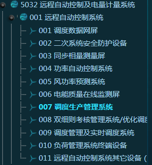
- When wind farm capacity is no less than 40 MW, configure the synchronous phasor measurement screen.
- When it is a distributed wind farm, do not configure automatic power control system or wind power prediction system.
- If the wind farm is located in the Henan province:
- Delete the dispatching production management system and add dispatching management and real-time dispatching system.
- Secondary system security protection device: Add a firewall, a forward isolation device, a reverse isolation device, and an invasive detection device.
- When the wind farm is located in North China, configure the double bylaws assessment system/optimization dispatching system.
Electric energy measurement system

Level 0.5S in electric energy meter
When the high-voltage side is connected by wire-transformer group wiring, the quantity is a sum of those of main transformer ingoing switch cabinet, feeder switch cabinet, reactive power switch cabinet, station transformer switch cabinet, ground transformer switch cabinet, and ground transformer (plus with station transformer requirements) switch cabinet.
When the high-voltage side is connected by single busbar wiring, the quantity is a sum of those of main transformer ingoing switch cabinet, feeder switch cabinet, reactive power switch cabinet, station transformer switch cabinet, ground transformer switch cabinet, ground transformer (plus with station transformer requirements) switch cabinet, and high-voltage main transformer ingoing gap.
Substation Civil Engineering Design Guide
This section offers you the design guide related to the civil engineering content in substation feasibility study based on electric professional design.
- Modify the value of design earthquake accelerating speed in Section 8.5.2 of feasibility study report as the value of project region seismic oscillation peak accelerating speed.
- When the productization of basic wind speed of substation has not been completed, modify the design basic wind speed in Section 8.5.2 of feasibility study report according to design guide 3.
- Continued for Item 2, the value of design basic wind speed is calculated by the value of basic wind pressure within 50 years displayed in the fifth column of the attached table, Substation Location Basic Wind Speed Reference Table (Appendix E: construction structure load regulation). The formula is: Basic wind speed = sqrt (1600 × basic wind pressure). If there is no city in the attached table, locate at the nearest city as a substitute.
- When the first-layer earth of formation lithology is thicker than 3 m and the subgrade bearing capacity is good enough as shown in Section 3.3, use natural subgrade in Section 8.5.2 of feasibility study report and switch to Item 4. Or else, delete the content of ‘natural subgrade, and the subgrade bearing capacity characteristic value…’ and ‘deal with it according to actual situation when the geological condition is not good’. Add the following content: ‘As the first-layer earth is soft with low bearing capacity, add six PHC-600AB110 reducing piles of 6 m under the prefabricated cabins and device foundations. Under the roads within the station region, replace with thick lime and soil for subgrade treatment’, and then continue with Item 6. If it is 10 kV switching station, delete ‘and device’ in the content above.
- Continued for Item 4, modify the subgrade bearing capacity characteristic value as that of first-layer earth bearing capacity.
- Continued for Item 4, add engineering quantity of PHC-600AB110 reducing pile under the prefabricated cabins and device foundations in the main engineering quantity list of Section 8.5.3, and correspondingly add it under prefabricated cabins and device foundations in online PBOM.
- Define the value of ‘no impact of underground water’ in Section 8.5.2 of feasibility study report according to the value of groundwater depth in Section 3.3. When the value of groundwater depth is larger than 3m, define it as no impact. When the value is less than 3m, define it as with impact of underground water.
- Define the value of ‘no erosive effect of site earth to concrete and rebar’in Section 8.5.2 of feasibility study report according to whether the groundwater and earth are erosive as described in Section 3.3. The erosive effect consists of no erosive, micro erosive, and medium erosive.