PBOM and Estimation
After you select the scheme, double-click the substation scheme object to view the corresponding PBOM. If you change your scheme selection, click the Generate button to generate new PBOM. If the scheme is not changed, do not click Generate. Or else, the manually modified PBOM parameters would be overwritten.
Electric I
- Main transformer system

The main transformer capacity here should be in accordance with that defined in current-period capacity.
- High-voltage XX gap
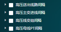
The wiring forms of 'wire-transformer group' and 'single busbar' are substitutes for each other. Single busbar wiring is consisted of outgoing circuit gap, PT gap, and main transformer ingoing circuit gap.
- Output and measure switch cabinet

The switch station owns this device, and the booster station does not.
- Section switch and disconnecter switch cabinet

This object exists only in the single busbar section switch wiring form (two main transformers). Connect section switch cabinet to Section I of busbar and disconnecter switch cabinet to Section II of busbar.
- Reactive compensation system

It is configured based on 20% - 30% of the main transformer capacity. In common conditions, configure only SVG. In the following two situations, consider configure FC:
- When Reactive compensation capacity is too large and the SVG cost is too high (for example, the Reactive compensation capacity is larger than 25 Mvar).
- Access system requires specific filter performance, so configure FC with filter capacity.
- Various cabins
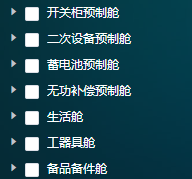

Increase or decrease cabins for the specific project. The change of any cabin might lead to variation of electric general layout drawing. Make record of the changes of this kind and inform electric professionals to update the drawings.
- Land acquisition area

In actual projects, the acquired land type and area should be determined by site land type, terrain, and gradient conditions. The value given in the scheme are referential. Verify with civil engineering professionals for final result.
Electric II
- Measurement and control device
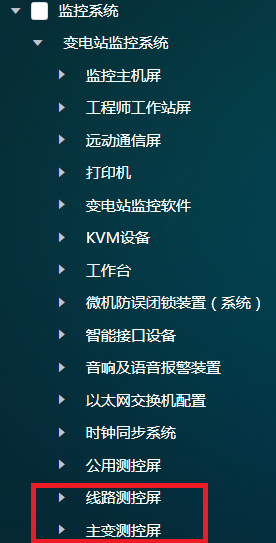
Configure the measurement and control screen according to main wiring gap type from the Electric I configuration.
- Circuit measurement and control screen:
When high-voltage outgoing circuit gap minuses the quantity of enclosed-type assembled switch gear is n, multiply each material quantity of circuit measurement and control screen by n.
When high-voltage outgoing circuit gap minuses the quantity of open-type power distribution device switch gear is n, multiply each material quantity of circuit measurement and control screen by n.
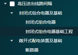
Enclosed type and open type are substitutes for each other and cannot coexist.
- Main transformer measurement and control screen: When the number of main transformers is n, multiply each material quantity of main transformer measurement and control screen by n.

- Circuit measurement and control screen:
- Protection device
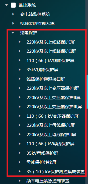
- Circuit protection screen (including 220kV, 110kV, and 66kV):
When high-voltage outgoing circuit gap minuses the quantity of enclosed-type assembled switch gear is n, multiply each material quantity of circuit protection screen by n.
When high-voltage outgoing circuit gap minuses the quantity of open-type power distribution device switch gear is n, multiply each material quantity of circuit protection screen by n.
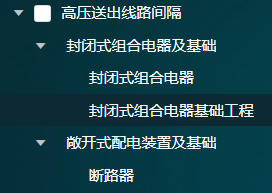
Enclosed type and open type are substitutes for each other and cannot coexist.
- 35kV circuit protection screen:
When the quantity of outgoing circuit and switch cabinet is n, multiply each material quantity of 35kV circuit protection screen by n.
No shield sets is needed and there is no material. This is the default manner in the model.
The two manners introduced above are substitutes for each other.

- Transformer protection screen (including 220kV, 110kV, and 66kV):
When the number of main transformers is n, multiply each material quantity of transformer protection screen by n.
- Busbar protection screen (including 220kV, 110kV, and 66kV):
Do not configure wire-transformer group wires.
By default, configure one set of single-busbar wire.
- 35/10kV integrated device for protection and measuring control

- Circuit protection device is applied in the following two situations:
Only when it is taken as switching station, configure circuit optical fiber differential protection + circuit current protection device. In other situations, configure only circuit current protection device.
Circuit optical fiber differential protection (35kV/10kV): When it is taken as 35kV or 10kV switching station and the quantity of 35kV circuit protection screen is 0, its quantity is the same as that of outgoing circuit switching cabinet.
Circuit current protection device (35kV/10kV): Its quantity is the same as that of switching feeder cabinet.

- SVG protection device is applied in the following two situations:
When the SVG set device is direct screening, the SVG protection and measuring control device uses current protection material and the quantity is the same as that of the SVG set device.
When the SVG set device is pressure decreasing, the SVG protection and measuring control device uses differential and backup protection material and the quantity is the same as that of the SVG set device.

- Capacitor protection device
While configuring FC set device, use capacitor protection and measuring control device, and its quantity is the same as that of the SVG set device.

- Buscouple (section) protection device
Its quantity is the same as that of section switch cabinet.

- Backup power source automatic input device
Its quantity is the same as that of section switch cabinet.
- Circuit protection device is applied in the following two situations:
- Circuit protection screen (including 220kV, 110kV, and 66kV):
- Remote automatic control system
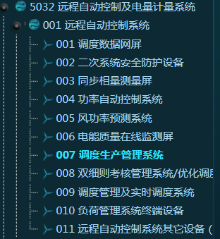
- When wind farm capacity is no less than 40 MW, configure the synchronous phasor measurement screen.
- When it is a distributed wind farm, do not configure automatic power control system or wind power prediction system.
- If the wind farm is located in the Henan province:
- Delete the dispatching production management system and add dispatching management and real-time dispatching system.
- Secondary system security protection device: Add a firewall, a forward isolation device, a reverse isolation device, and an invasive detection device.
- When the wind farm is located in North China, configure the double bylaws assessment system/optimization dispatching system.
- Electric energy measurement system
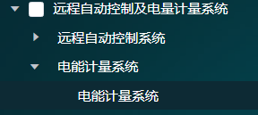
Level 0.5S in electric energy meter
When the high-voltage side is connected by wire-transformer group wiring, the quantity is a sum of those of main transformer ingoing switch cabinet, feeder switch cabinet, reactive power switch cabinet, station transformer switch cabinet, ground transformer switch cabinet, and ground transformer (plus with station transformer requirements) switch cabinet.
When the high-voltage side is connected by single busbar wiring, the quantity is a sum of those of main transformer ingoing switch cabinet, feeder switch cabinet, reactive power switch cabinet, station transformer switch cabinet, ground transformer switch cabinet, ground transformer (plus with station transformer requirements) switch cabinet, and high-voltage main transformer ingoing gap.