
Optimizing Layout
-
Select Layout Optimization from the
Calculation Type drop-down menu.
Figure: Layout Optimization Pane 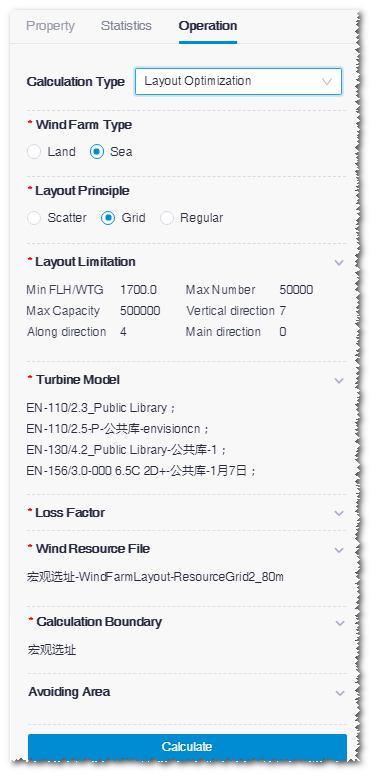
-
Click the expand icon
 in the Wind Farm Type area
and select Onshore or
Offshore.
If you select Offshore, no
Map option is available.
in the Wind Farm Type area
and select Onshore or
Offshore.
If you select Offshore, no
Map option is available.
-
Click the expand icon in the Layout Principle area
and select Scatter, Grid, or
Regular.
- Scatter: This option is applicable for hilly areas or flat areas with limitations. The turbine layout scheme is customized according to your optimization target.
- Grid: This option is applicable in wind farm with average-level resource. The turbine layout scheme is customized according to the direction and space you defined.
- Regular: This option is applicable in wind farm with average-level resource. The turbine layout scheme with regular layout and optimal power production is provided for solutions.
-
Click the expand icon in the Layout Limitation
area and input the following parameters:
Table 1. Layout Optimization Parameters Name Description Applicable Layout Target Type Three options are available: AEP, IRR, and NPV. Scatter and regular Min FLH/WTG Minimum power production hours of a turbine Scatter, grid, and regular Max Capacity Maximum capacity of wind farm Scatter, grid, and regular Max Number Maximum No. of turbines recommended for a wind farm Scatter, grid, and regular Max wake loss/WTG Maximum wake loss of a turbine Scatter, grid, and regular Max wake loss/WF Maximum wake loss in wind farm Regular Min space Minimum space between turbines Scatter and regular Vertical direction Space between turbines vertical to main wind direction Grid Along direction Space between turbines along main wind direction Grid Array direction Main wind direction angle Grid and regular Direction buffer Set up direction buffer while you set the main wind direction manually. Regular -
Click the expand icon in the Wake Effect area and
select wake model and wake decay factor.
Note: This module is displayed only when you select Regular.You can select Park Model or Advanced Park Model.
-
Click the expand icon in the Turbine Type area and
select the turbine models to be optimized.
All turbine model series which contain common turbine models are listed, and you can select more than one.Note: You need to configure in advance the following parameters in the Operation pane of the turbine series: name, rated power, rotor diameter, vave, and turbine price. For details of the configuration, refer to the section Configuring Turbine Model Series.
-
Click the expand icon in the Wind Resource File
area and select a file in the list.
All wind resource files in the project are listed, and you can select one.
-
Click the expand icon in the Loss Factor
area.
-
Click the expand icon in the Calculate Boundary section and select
boundary object(s).
All the boundary objects in the project are listed, and you can select more than one.
-
(Optional) Click the expand icon in the Nearby Wind Farm
area, select nearby wind farm(s), and configure the selected wind farm(s) to
calculate the wake influence between the current wind farm and nearby wind
farm(s).
Note: The settings in this area are not mandatory. If no wind farm is nearby, skip Step 15-16.Note: This module is displayed only when you select Regular.
- Select the wind farm object in the list. The options in the list are wind farm objects in the project other than the current wind farm.
- Click the Config button at the right side of selected wind farm to open the corresponding overview page.
- Set up the turbine model, hub height, and power curve of each turbine in the table.
- Click Save.
-
(Optional) Click the expand icon in the Map section and
select a map.
All the maps in the project are listed, and you can select one.