
Configuring Parameters and Calculation
- Click the self-built substation object in the project pane.
-
Click the expand icon 《 to open the operation pane.
The calculation type is automatically selected according to the defined
construction nature.
- When the construction nature is New, the calculation type is Substation design
- When the construction nature is Extension, the calculation type is Extension substation design
For more information of substation construction nature, refer to the section Modifying Substation Properties.
Note: The instructions above are applicable only when the self-built substation type is Traditional Substation. When the self-built substation type is Inner tower substation or Out tower substation, no matter whether the construction nature is New or Extended, you need to select the calculation type as Substation design or Extension substation design manually.
New Substation Design
The parameters to be configured for new substations are show as in the following figure:

-
Select associated power line scheme.
All power line scheme objects in the projects that have completed
power line design are listed in the option list.Note: The scheme you select here MUST be the power line scheme whose electric single-line graph is matched with the current substation.
-
Select substation scheme.
-
Select basic information of the scheme, and specify the capacity
and construction plan of the substation.
Five plans are listed in the menu:
- 10 kV, current period 0 main transformer, forward 0 main transformer: Total capacity of substation is 10 kV. One switching station is planned for current period, and no long-term plan.
- 35 kV, current period 0 main transformer, forward 0 main transformer: Total capacity of substation is 35 kV. One switching station is planned for current period, and one switching station is for long-term plan.
- 110 kV current period 1 main transformer, forward 1 main transformer: Total capacity of substation is 110 kV. One main substation is planned for current period, and one main substation is for long-term plan.
- 110 kV current period 1 main transformer, forward 0 main transformer: Total capacity of substation is 110 kV. One main substation is planned for current period, and no long-term plan.
- 220kV current period 1 main transformer, forward 0 main transformer: Total capacity of substation is 220kV. One main substation is planned for current period, and no long-term plan.
-
Input the values of current capacity and long-term capacity.
Note: When there is no long-term plan, the corresponding field is disabled.
-
Select a substation scheme option.
Five options are provided for substation design, each one of
which is corresponding to one of the options in substation
information.
- When the current capacity and long-term capacity you input are both within the regulated range, the corresponding substation design scheme automatically displays in this field.
- If the values of capacity are out of range, no scheme is available.
Table 1. Capacity Range of Substation Design Substation Plan Substation Design Scheme Current Capacity Range Long-Term Capacity Range 10 kV, current period 0 main transformer, forward 0 main transformer Scheme 27: 10 kV, 10 MVA, 1回送出, 预制舱 0 - 20 35kV, current period 0 main transformer, forward 0 main transformer Scheme 1: 35kV, 40MVA, 1回送出, 预制舱 0 - 40 0 - 40 110kV, current period 1 main transformer, forward 1 main transformer Scheme 6: 110kV, 1*50MVA+1*50MVA, 1回送出, 预制舱 31.5 - 63 31.5 - 63 110kV, current period 1 main transformer, forward 0 main transformer Scheme 2: 11kV, 1*50MVA, 1回送出, 预制舱 31.5 - 63 220kV current period 1 main transformer, forward 0 main transformer Scheme 14: 220kV, 1*100MVA, 1回送出, 预制舱 100 - 125 - Click the Done button to save the changes.
-
Select basic information of the scheme, and specify the capacity
and construction plan of the substation.
Five plans are listed in the menu:
-
Select field leveling and entrance route design.
- No design: Design only the substation and on other parameters are required.
- Optimization: Other than designing the substation, added entrance route and field leveling calculation. You need to configure both field leveling and entrance route design parameters, and select entrance route start point, map, route planned area, and prohibited area.
- Engineering quantity calculation: Other than designing the substation, calculate route engineering quantity based on route and route design parameters and calculate field leveling engineering quantity based on elevation and substation area. You need to configure field leveling and entrance route design parameters and select map.
The operations to configure parameters are shown as in the following steps. Configure the required parameters according to the field leveling and entrance route design scheme you selected.
- Configure field leveling design parameters, including highest water level, excavation slope ratio, and backfill slope ratio.
- Configure entrance route design parameters, including hardened surface condition, excavation slope ratio, and backfill slope ratio.
- Configure entrance route start point. The options for Design road are all route objects under the project, and the options for Existing road network are all road network objects under the project.
- Select route planned area. All polygon objects are listed as options.
- (Optional) Select prohibited area. The options are all areas defined as protection zone, height restrict area, etc.
Note: If you select Optimization, you must complete setup of vertexes, the entrance route start point and vertex coordinate must be within the route planned area, and the map must cover the route planned area and be expanded by 200m. Or else, the calculation cannot be done.Note: If you select Engineering quantity calculation, you must complete setup of vertexes and elevation, the map must cover the entrance route and field leveling area (expanded by 200m), and the entrance route and field leveling must be crossed or touched. Or else, the calculation cannot be done. -
Click Calculate to submit the calculation
task.
As you select different field leveling and entrance route design schemes, the calculation process and result varies:
- If you select No design, the calculation result is generated directly according to the substation scheme you selected. No calculation task is submitted, the PBOM result is available immediately. Refer to Checking PBOM Result for more information.
- If you select Optimization, other than substation design, the entrance route and field leveling calculation is added. The calculation task is submitted. After the task is completed, you can check the entrance route design and field leveling design. Continue with Step 5.
- If you select Engineering quantity calculation, other than substation design, the entrance route and field leveling engineering quantity calculation is added. The calculation task is submitted. After the task is completed, you can check the PBOM result. Continue with Step 5.
- Choose Tools Library > Task List.
- Select Inbound Road and Level Design (only for Optimization) or Calculation of Inbound Road and Level Engineering Quantity (Only for Engineering quantity calculation) in the task type to check the task progress. When the progress reaches 100%, you can check the result. Refer to the section Checking the Calculation Result for details.
Extension Substation Design
The parameters to be configured for new substations are show as in the following figure:
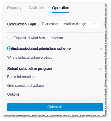
- Select the extension substation type as Expanded wind farm substation or Expanded user substation
-
Select associated power line scheme.
All power line scheme objects in the projects that have completed
power line design are listed in the option list.Note: The scheme you select here MUST be the power line scheme whose electric single-line graph is matched with the current substation.
-
Select substation scheme.
- If you select Expanded wind farm substation, you need to select basic information, and specify the No. of new main transformer and New 35kV busbar values. Their mapping relationships are listed in the following table:
Scheme Outlet Voltage (kV) Inlet Voltage (kV) No. of new main transformer New 35kV Busbar 1 220 35 1 1 2 220 35 0 1 3 220 35 0 0 4 110 35 1 1 5 110 35 0 1 6 110 35 0 0 7 35 35 / / 8 10 10 / / Note: After you configured basic information and corresponding No. of new main transformer and New 35kV busbar, the available substation scheme appears automatically in the Options menu. Select this scheme and save the settings.- If you select Expanded user substation, you need to select basic information, and specify the grid-connected voltage value. Their mapping relationships are listed in the following table:
Scheme Outlet Voltage (kV) Inlet Voltage (kV) Grid-Connected Voltage (kV)
1 110 35 35 2 110 10 10 3 35 35 35 4 35 10 35 5 35 10 10 6 10 10 10 Note: After you configured basic information and corresponding grid-connected voltage, the available substation scheme appears automatically in the Options menu. Select this scheme and save the settings. -
Click Calculate.
Note: As the extension substation design applies the schemes saved in the system. After the calculation starts, the PBOM information is immediately generated. Refer to Checking PBOM Result for details.