After the wire optimization has been completed, check the wire route in GIS and
parameters in the Overview page. According to the specific project
situations, you can adjust the wires if necessary.
-
Click the check box before the power line scheme object.
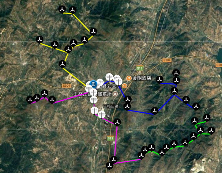
The optimized power line layout is displayed in GIS, and the legend is
at the left bottom.
-
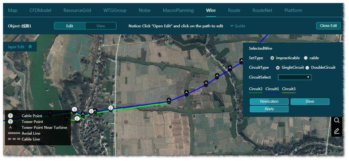
Expand the Layer Edit pane and click the
Wire tab.
-
Click the Edit tab (default).
-
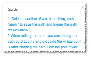
Expand the Guide pane to view the operation guide for
editing wires.
-
Click the Edit button. The wire paths are editable
now.
-
Edit the wires.
-
Click a section of the wire.
-
Click the Edit Path option on the wire. The
control nodes appear.
-
Drag the control nodes to modify the direction and location of wire
path.
Note: For double circuit, if you modify one of the wire path, the other one will
not change. But after the calculation, the other wire path will be the same
as the modified one.
-
Delete a wire.
-
Click a section of the wire.
-
Click the Delete Path option to delete this wire
section.
-
Modify path properties.
-
Delete the path to be modified with the method introduced in Step
7.
Note: To modify the property of a path, you need to delete the original
path, select the properties, and draw a new path. If the path to be
modified is double-circuit, delete both the two circuits.
-
Select the erection form, circuit type, and circuit in the property
panel at the right top of GIS.
-
Click one end of the cable/tower/substation deleted in Step a.
-
Click the pop-up Draw Path option.
This end is taken as the start point for drawing a
path.
-
Double-click to finish drawing.
-
Drag the control nodes of the drawn path to adjust its direction and
location.
Note: The end point should be located at the other end of the
cable/tower/substation deleted in Step a.
Note: If you want to draw a double-circuit path, select
Double Circuit and assign the circuit in
the property panel, and draw one wire path. After calculation, two
circuits are displayed.
-
(Optional) Click the Save button to save all current
modifications.
If the wire paths are only saved but not re-calculated, when you refresh
the browser and check the power line scheme again, a message pops up:
The wire paths have been modified. Do you want to show them in
edit mode?
You have two choices:
- Click OK to enter the edit page of saved wire
paths.
- Click Cancel to show the wire paths after last
calculation.
-
(Optional) Click the Revocation button. All your actions
after the last wire optimization calculation are eliminated.
-
Click the Apply button.
All the modifications are saved and the wire optimization task is
submitted.
-
After the calculation, click the check box before the power line scheme object
to view the wire paths after modification.
Note: It is recommended to click Apply only after you
complete all modifications on the wire paths in order to reduce calculation
times for time saving.
Note: All the actions will not be revocated after you click
Apply.
-
Click the Close Edit button to finish wire path
modification.
-
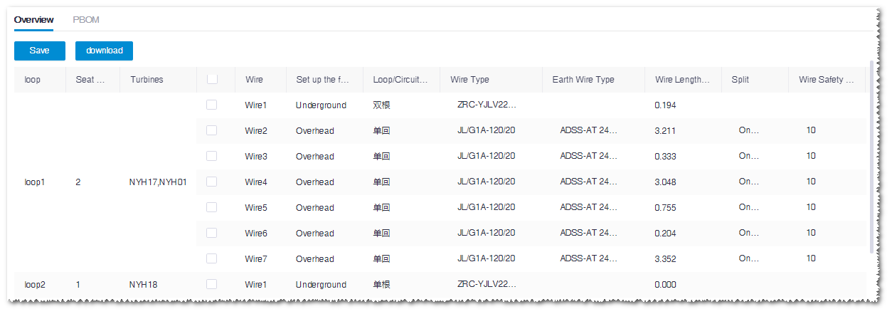
Double-click the power line object to open the Overview
page.
The information displayed in the Overview page
includes power line type, wire type, earth wire type, wire length, path
length, split, wire safety coefficient, earth wire safety coefficient.
-
Click the Download button to export the overview
table.