
Configuring Parameters and Starting Calculation
Wire optimization needs the information of WTG group layout, boundary, map, avoiding range, substation location, route scheme, road network, preferences, and erection form.
- Click the power line scheme object in the Project pane.
- Click the expand icon 《 to open the operation pane.
-
Click the Operation tab.
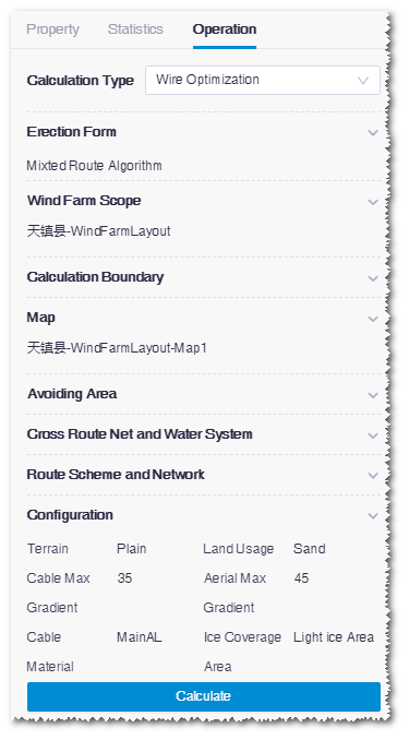
- Select Wire Optimization as calculation type.
-
Select wire erection form.
The default option is Mixed Route Algorithm. Cable Route Algorithm and Aerial Route Algorithmare available in the drop-down menu.
-
Select the WTG group file as layout.
In the option list, all the WTG group objects in the project are
displayed.
Note: To apply the selected WTG group, you must in advance configure its turbine model series (refer to Configuring Turbine Property) and the rated power in the property pane of the turbine model series (refer to Checking Turbine Model Series Property).
- Select a wind farm boundary file to define the calculation boundary.
- Select a map. The options in the drop-down list are map objects manually imported or downloaded from Greenwich.
-
Select the scopes to be avoided for the Aerial avoiding
range and Cable avoiding area
fields.
Because the requirements of aerial and cable are different, you should select the avoiding scopes respectively for them.
For each type of avoiding scope, you need to set up database and customized avoiding scopes:If no scope is to be avoided, skip this step.- Public avoiding database: The avoiding areas saved in the system database are listed
- Custom avoiding area: All area objects customized by user other than wind field are listed
-
Select cross route network and river system.
The purpose of this selection is to calculate the cross times between
power lines and route network or river system.
- The options of cross route network are road network data from Greenwich, imported road network files, and road network object downloaded or drawn within Greenwich.
- The option of cross river system is the river system database from Greenwich.
- Select the route scheme and road network. Route scheme and road network comprise the route information. Route scheme includes the route designed by Greenwich, and road network is the existing road imported from other sources, or downloaded or drawn in Greenwich. For more information, refer to the section Route and Platform Design. In the Cable Route Algorithm and Mixed Route Algorithm erection forms, you must input the route scheme and road network. For Aerial Route Algorithm, you can skip this step.
-
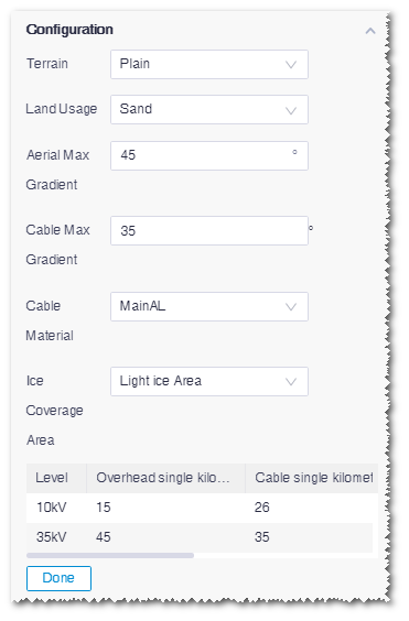
Set up the configuration parameters.
Parameters are displayed with default values. Modify them if
necessary.
- Click Calculate to submit the calculation task.
- Choose Tools Library>Task List to check the task status. When the process reached 100%, the calculation is completed.