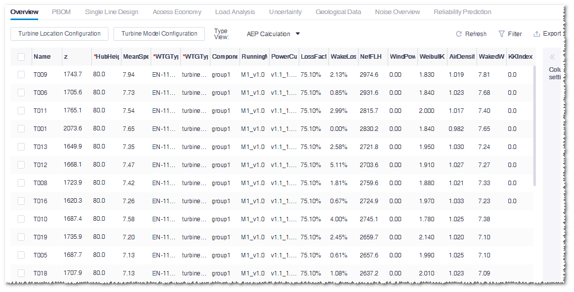
After import of wind farm layout and selection of turbine model, check and edit the property of each turbine.
Double-click the WTG group object in the project pane. The WTG group
Overview page opens in the information demonstration
area.Figure: WTG Group Overview Interface
The main parameters are shown in the following table:
Table 1. Main Turbine Parameter Introduction
Name
Description
z (Elevation)
Derived from calculation and no modification is needed
generally
Hub height
The vertical distance from center of turbine hub to
ground. Click the Turbine Location
Configuration button to edit it.
Mean speed
Derived from calculation and not editable
WTG type series
Click the Turbine Model
Configuration button and select the turbine
model series in the pop-up window.
WTG type
Click the Turbine Model
Configuration button and select the turbine
model series in the pop-up window. The options in the
drop-down menu are turbine models embedded in the selected
turbine model series.
Running mode
Click the Turbine Model
Configuration button and select the turbine
model series in the pop-up window. The options in the
drop-down menu are operation modes embedded in the selected
turbine model.
Power curve.
Click the Turbine Model
Configuration button and select the turbine
model series in the pop-up window. The options in the
drop-down menu are power curves embedded in the selected
operation mode.
Component group
Click the Turbine Model
Configuration button and select the turbine
model series in the pop-up window. Refer to Configure component groups.
Sound power level version
Click the Turbine Model
Configuration button and select the turbine
model series in the pop-up window. The options in the
drop-down menu are noise power level versions embedded in
the selected operation mode.
Loss factor
Set it up in the Operation
pane
Wake loss
Derived from calculation and not editable
Equivalent full-load hours
Derived from calculation and not editable
Length of tower sections
Tower foundation configuration embedded in turbine model.
Click the Turbine Model Configuration
button and check in the applicable tower
KK index
The KK index is a terrain risk level index derived from
the study of mapping relation between terrain
characteristics in historical typical wind farms and the
corresponding failure probability. Currently, 12 grades of
this index are available providing reference for turbine
model selection and future failure prediction.
This index
is applicable only to AEP calculation.
Click an option in the Type View menu.
The available options are AEP Calculation,
Layout Optimization, Noise
Calculation, and EBA.
Expand the Column Settings list to select more
parameters into the table.
Edit the turbine location information.
Click the Turbine Location Configuration
button.
The HubHeight, x,
and y parameters are editable.
Edit the parameters.
Click Save to save the modifications.
Note: To modify turbine location parameters of multiple turbines, select
multiple turbines in the check box or click in the check box at the
left top of the table to select all turbines. Click the
Turbine Location Configuration button and
edit the parameters of one turbine. The corresponding parameters of
all selected turbines are modified.
Configure turbine model parameters.
Click the Turbine Model Configuration
button.
Select turbine(s).
Click the Configuration button. The
Turbine Model window opens.
Select turbine model series, turbine model, and tower.
Select operation mode in the Operation Mode
Selection tab.
Select power curve and noise curve for each turbine.
Note: Select multiple turbines to set up the power curve and noise curve
by group. During batch configuration, if the selected turbine has
been configured, a message pops up to ask whether to overwrite the
original turbine model configuration.
Select component group in the Component
Selection tab.
For details, refer to Configure
component groups.
Click the Tower Select tab.
(Optional) Select the filter conditions, such as foundation type,
extreme wind speed, maximum length of sections, or maximum weight of
sections, to find the desired tower(s).
Select a tower.
Note: The hub height of e the selected tower must be coherent with that
of the turbine model.
Click Done to save the modification.
Tip: Because some parameters are included in others, it is
suggested to set up the following parameters in sequence: turbine
model series, turbine model, operation mode, power curve, noise
power level version. Besides, select component group and tower after
you select turbine model.
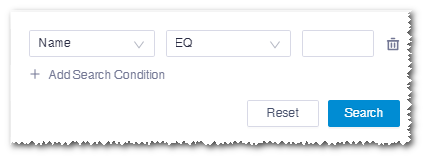
Click Filter to search by a specific turbine model or
parameter.
Click Export>Export Table to
export the current table into an Excel table in the default download directory
of your browser.
Select some turbine locations and click Export >
Export Time Series to export a tim file with 10 min
time series of the selected turbine locations, including wind speed, wind
direction, waked wind speed, and gross energy.