
Checking Tower Layout Result
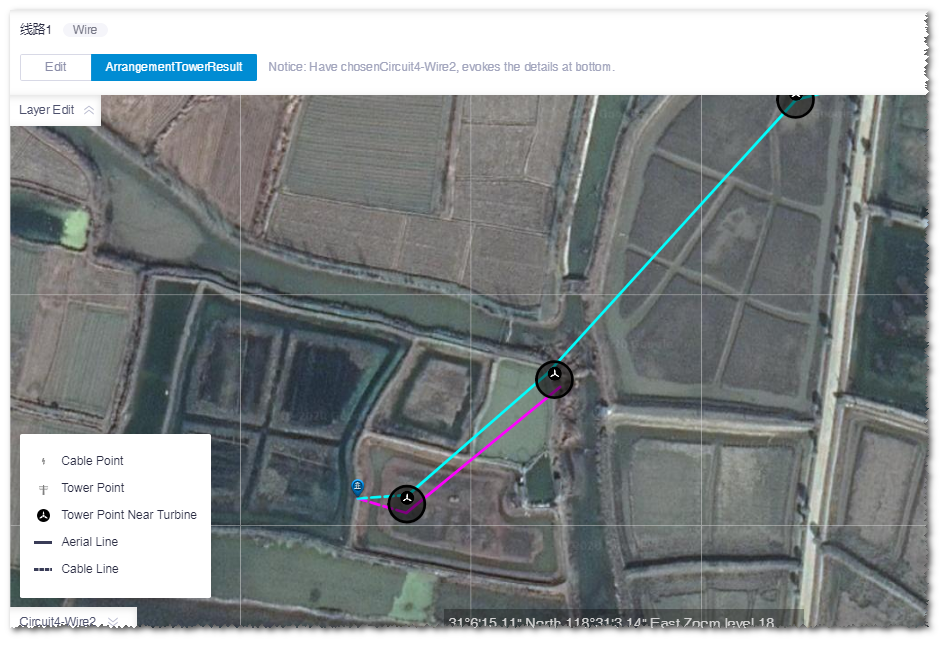
- After the calculation is completed, click the check box before the power line scheme object. The power line layout is displayed in GIS, and the legend is at the left bottom of GIS.
- Expand the Layer Edit panel at the left top of GIS.
-
Click the ArrangementTowerResult tab.
-
Click a wire in the layout. The tower layout in this wire is displayed.
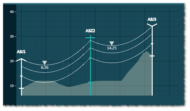
An example of Circuit2 - Wire2 is shown in the figure below:
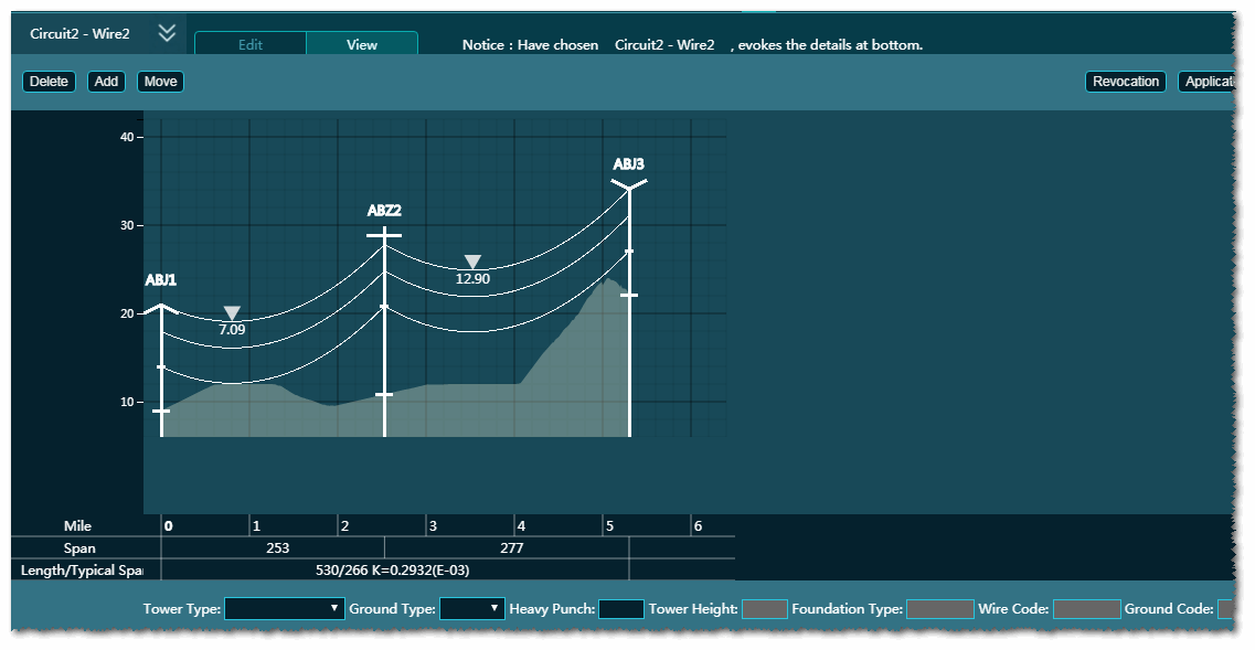
In the tower layout graph, the parameters of Mile, Span, and Length/Typical Span are displayed.
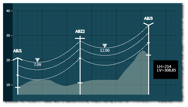
When the pointer hovers over the tower, a auto-tip appears showing the horizontal and vertical spans.
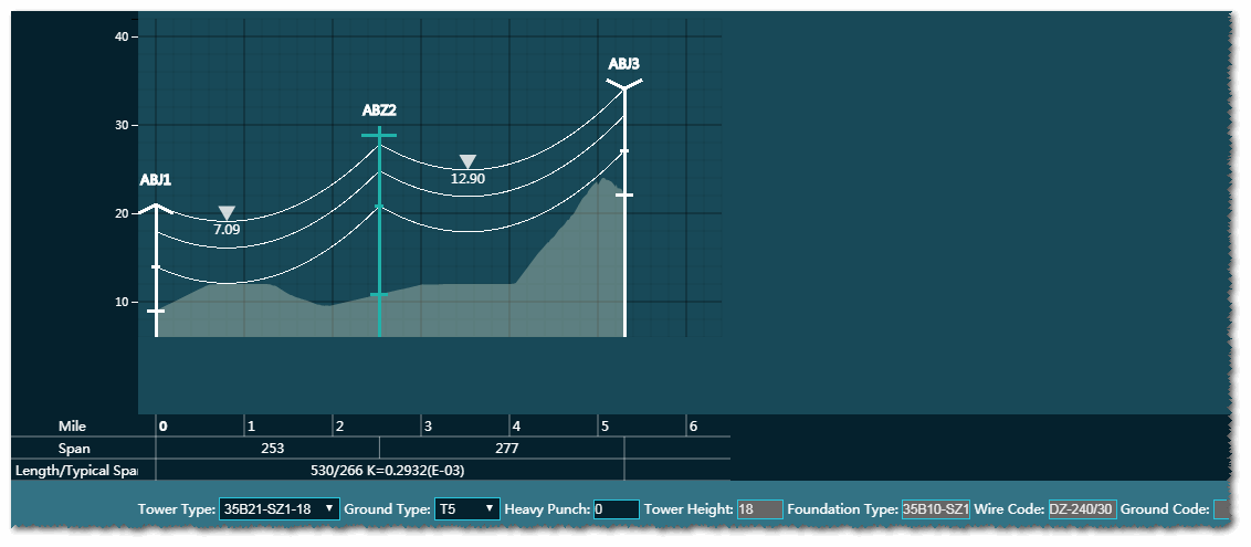
Click a tower. The tower type, ground type, heavy punch, tower height, foundation type, wire code, and ground code of this tower are displayed at the bottom line.
-
(Optional) Click the Delete, Add,
and Move button to edit the towers.
-
Click the Delete button, select a tower, and
click Apply to delete this tower.

- Click the Add button, input the parameters at the bottom, and click in the graph. A new tower is added.
-
Click the Move button, select a tower, input the
distance, and click the Left or
Right button. The selected tower is moved by
the defined distance.

The figure below shows the tower after moving.
-
Click the Delete button, select a tower, and
click Apply to delete this tower.