
Configuring Operation Parameters and Starting Calculation
For substation siting, the following items need to be prepared for configuration: WTG group layout, substation information configuration, siting boundary, map, avoiding scope, existing road network, and preference setup. The user interface is shown as in the figure below:
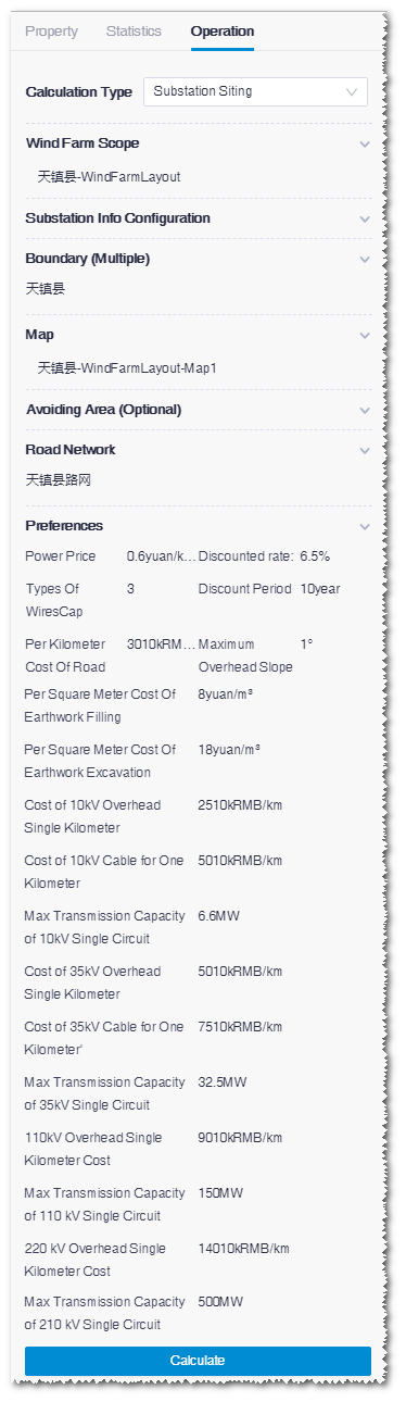
-
Select WTG group layout.
In the option list, all the WTG group objects in the project are
displayed.
Note: To apply the selected WTG group, you must in advance configure its turbine model series (refer to Configuring Turbine Property) and the rated power in the property pane of the turbine model series (refer to Checking Turbine Model Series Property).If you need to create a new WTG group object, perform the following steps:
- Import a WTG group layout file.
- Select its projection, zone and datum.
- Input its name.
-
Click Import to import it into the project.
For details, refer to the section Importing Turbine Layout.
-
Configure substation information.
- Click the Open Configuration Panel button in the Substation Info Configuration area to open the Substation Info Confighkuration window.
-
Click the Acquire Substation Info button. The
self-built substation information from the electric single-line graph is
loaded in the table, including substation type (only applicable for
electric single-line graph generated by access plan), grid-connected
substation, ingoing and outgoing circuit voltage.
For more information of electric single-line graph, refer to the
section Access Plan Design.
Note: Items to be filled are marked by red rectangle.
- (Optional) Select candidate substations to edit them in group.
-
Select candidate substation type.
The options are:
- Grid-connected device within tower
- Grid-connected device outside tower
- Substation
If the electric single-line graph you acquired is generated by access plan algorithm, the substation types are loaded automatically from access plan. You can modify them when necessary.
If the electric single-line graph you acquired is edited manually, select the self-built substation type manually.
After you select substation type, the length, width, and cost of the candidate substation are loaded automatically.
- (Optional) Modify No. of main transformer. The default value is 1. After your modification, the length, width, and cost of the substation are updated automatically.
-
Select self-built outlet circuit.
- If the outlet circuit is self-built, select Yes to include it in the cost calculation. The outlet circuit cost will be displayed in the result overview.
- If the outlet circuit is not self-built, select No to exclude it in the cost calculation.
Note: Only when the grid-connected substation information is loaded for the candidate substation, you are enabled to select the self-built outlet circuit status. Or else, this option is disabled.When you select Yes, the value of Cost of Outlet Circuit is automatically loaded from the template.
- Click the Apply button to save the settings. The information, including quantity of candidate substations, ingoing and outlet circuit voltage level, grid-connected substation, etc., is verified by the system. If any information is not consistent with that in electric single-line graph, a warning pops up for the details and the corresponding item is marked in red. After you modify the inconsistency, the verification is performed again and settings are saved.
-
Define the substation siting boundary.
The substation siting boundary should be within the map.
In the option list, all the polygons saved in the project are displayed. If you need to draw a new one, refer to the section Drawing a Polygon for details.
-
Select map: Import a map manually or generate a map file by macrositing.
In the planning and siting phase, the map file is generated by macrositing or downloaded from Greenwich. These two methods are introduced as follows:
- Method 1: Generate a map file by macrositing.
- Click the siting boundary object under the project.
-
In the Macrositing page within the
Operation pane, click the
Calculate button to start the
calculation.
After the calculation is completed, a map file is created within the project tree.
For details, refer to the section Macrositing.
- Method 2: Download the map from Greenwich.
- Check the siting boundary object in the project tree.
-
Click the data download icon
 in the
toolbar menu.
in the
toolbar menu.
- Select Download Type as Terrain, and select data source and contour interval.
- After the download is done, import the map file into the project. Refer to the section Creating a Terrain or Roughness Map based on Polygon.
-
Define avoiding scope.
Note: According to the project condition, if no scope is to be avoided, leave this section empty.
- For Avoiding Scope of Substation, Avoiding Scope of Circuit, and Avoiding Scope of Road, the items listed are polygons saved as protected areas, farmlands, buildings, military zones, oil and gas fields, and so on. For details, refer to the section Drawing a Polygon.
- For Avoiding Scope of Substation Tiff, Avoiding Scope of Circuit Tiff, and Avoiding Scope of Road Tiff, the items listed are existing substations, circuits, and roads from database.
-
Select existing road network: Download the existing road network from Greenwich
or draw a road network manually. These two methods are introduced as
follows:
- Method 1: Download road network from Greenwich
-
Click the data download icon in the
toolbar menu to open the download panel.
- Select the siting boundary object.
- Select the download type as RouteNet.
- Select Expressway, National Road, Provincial Road, Prefectural Road, and Low-Level Road as Route Level.
- Click the Download button to generate a road network object in the project.
- Method 2: Draw a road network manually.
-
Click the draw and measure icon
 in
the toolbar menu to add lines in GIS.
in
the toolbar menu to add lines in GIS.
- To save the lines, select type as Entrance Net, select Road grade as Low-Level Road, input the name, and click the Create button. For details, refer to the section Drawing a Line.
-
Set up parameters: Configure the parameters as shown in the figure below:
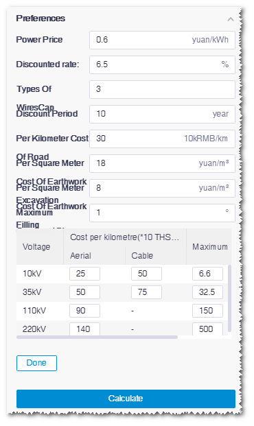
Note: The default cost of circuit at each voltage level and default value of maximum transmission capacity of single loop are given by the system. Click the table cell to modify the value. - Click Calculate after all the parameters and information are successfully configured.