Turbine Foundation Design
This chapter introduces the configuration and calculation process of wind turbine foundation design, aiming to help you quickly get acquainted with wind turbine foundation design and optimization in Greenwich.
Creating a Wind Farm
Click the project name for wind farm creation.
Click the Import/Export button
 .
.In the Create tab, select WTG group from the menu.
Click the Import radio button.
Click the Upload button to import the txt or kml file.
Select the coordination system.
Click Create.
After the creation, check the newly-created WTG group object under project or the turbines under it to show the location of turbines.
Geological and Load Data Configuration
This section introduces the way to configure geological and load data before the foundation calculation.
Importing Turbine Model and Configuring Load Data
- Select the project name for turbine model import in the Project pane.
- Click the Import Turbine Model Series button
 in the operation button area.
 - Select the turbine model to be imported in the Import Turbine Model Series page. Refer to the section Importing Turbine Model for details. After the import is completed, a new turbine model series object is added in the project. It contains the imported turbine model object.
- Double-click the turbine model series object in the project.
- Click the Applicable Tower tab. For details of configuring tower, refer to the section Configuring Applicable Tower .
- Double-click the turbine model object in the project.
- Click the Component Configuration Management tab. For details of configuring component group, refer to the section Configuring Component Group .
- Click the Foundation Load tab. For details of configuring load parameters, refer to the section Configuring Foundation Load . For foundation design, the turbine model parameters to be configured are listed in the table below:
| Configuration Object | Type | Parameter Name |
|---|---|---|
| Applicable tower | Basic information | Tower natural vibration period |
| No. of tower sections | ||
| Each section parameter | Section No. | |
| Length | ||
| Weight | ||
| Bottom flange | Flange radius under tower | |
| Tower wall | ||
| Exterior diameter of bottom flange | ||
| Bottom flange width | ||
| Bottom flange thickness | ||
| Bore diameter of anchor bolt | ||
| Component group | Nacelle | Nacelle weight |
Assigning Turbine Model
Double-click WTG group in the Project pane.
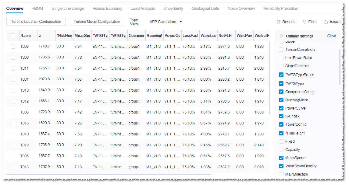
Click the Overview tab to display the wind farm overview page.
Select Tower Config and Component group in the Column Settings list. The corresponding column is added in the overview table.
Set up the values of hub height, turbine model series, turbine model, component group, and tower config in the table.
Click Save to save the settings.

Configuring Geological Data
Double-click the WTG group object in the Project pane.
Click the Geological Data tab to open the corresponding page.
Set up the values for Groundwater depth, Equivalent resistivity, and so on.
Generally, the Groundwater depth value is set as -10.
Click the Export layer template button, and edit the layer data in the template.
Click the Import layer data button.
Select the modified template in the pop-up window, and upload it by clicking the Upload button.
Check the imported data and click Save.
Foundation Calculation
This section introduces how to group the turbines in the wind farm, generate foundation scheme, and download design report and CAD drawings after data configuration described in the previous sections.
Foundation Grouping
Based on the configured load data and geological data, the turbines in the wind farm should be classified as groups for calculation.
Click the project name or the foundation folder for turbine foundation creation.
Click the Import/Export button
 in the operation button area.
Select Turbine foundation in the menu.
Input a name for the foundation.
Click Create to create a turbine foundation object in the project tree.
Click the turbine foundation object in the Project pane.
Click 《 to open the operation pane.
Click the Operation tab.

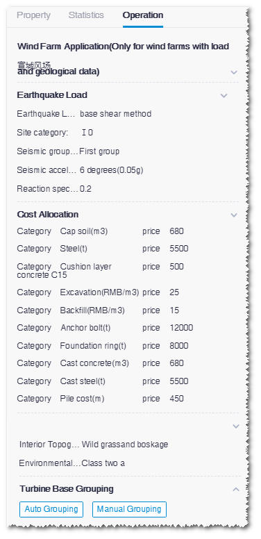
Set up wind farm, earthquake load, cost allocation, interior topography, and environmental class.
Click the Auto Grouping button. After the grouping is done, a window opens showing the groups.
Check the grouping result and manually adjust the grouping.
When the grouping is done, click the Save group button to save the changes.
Note
If the turbine model, load, and geological data have been modified, you should re-group the turbines, and the grouping result will replace the one from last calculation. If you want to preserve the last calculation result. It is suggested to create a new turbine foundation object and group the turbines again.
Foundation Optimization
Select a foundation object in the Project pane.
Click 《 to open the operation pane.
Click the Operation tab.
Set up calculation type, applied standards, foundation plan, foundation size, parameters, verify condition, and outgoing line type.

Note
For references to set up these parameters, see Greenwich Design Guide.
Click Calculate.
After the calculation is started, you can check the status in task list.
Choose Tools Library > Task List to open the task list page.
Select Turbine Foundation from the drop-down menu.
Click the Check button to see the task in the table.
Downloading Report and CAD Drawings
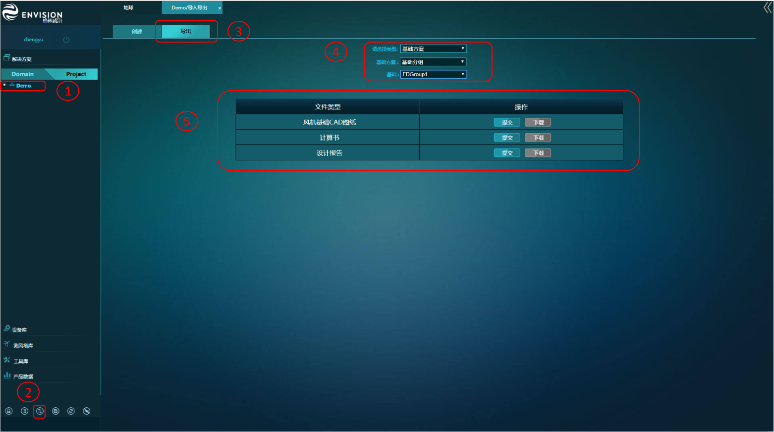
Click the project name.
Click the Import/Export button
 in the operation button area.
Click the Export tab.
Select Foundation scheme in the menu, and select the foundation scheme and foundation.
Click the Submit button in the specific File Type row. The corresponding download request is submitted.

Open Task List, and select Foundation CAD to check the CAD drawing export status.
Repeat Step 1-3 to re-open the Export page. If the export is completed, the Download button is enabled for downloading. Generally, the calculations and design reports export is done within 10s, and CAD drawings export is done in about 10 minutes.