Power Line Design
Power line design is to design and optimize the wires and their erection forms. This chapter introduces the operations related to power line design, including scheme creation, wire optimization, tower layout optimization, electric check, PBOM configuration, and CAD drawing generation.
Creating a Power Line Scheme
- Click the project name in the project pane.
- Click the Import/Export button
 in the operation button area to open the Import/Export page.
 - Click the Create tab, and select Electric scheme as the category.
- Input the value for Name.
- Click Create. The power line scheme is added in the project tree.
Wire Optimization
Wire optimization associates the actual situation of wind farm, configures relative prerequisites and parameters, and optimizes the wire route of power line.
Note
Before wire optimization, complete configuration of single-line design. Refer to the section Access Plan Design for more information.
Configuring Parameters and Starting Calculation
Wire optimization needs the information of WTG group layout, boundary, map, avoiding range, substation location, route scheme, road network, preferences, and erection form.
Click the power line scheme object in the Project pane.
Click the expand icon 《 to open the operation pane.
Click the Operation tab.
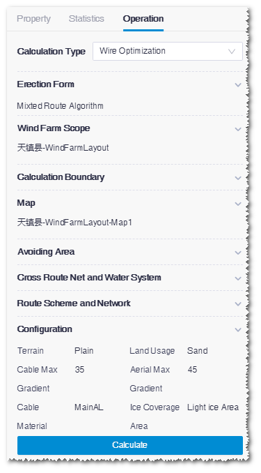
Select Wire Optimization as calculation type.
Select wire erection form.
The default option is Mixed Route Algorithm. Cable Route Algorithm and Aerial Route Algorithmare available in the drop-down menu.
Select the WTG group file as layout. In the option list, all the WTG group objects in the project are displayed.
Note
To apply the selected WTG group, you must in advance configure its turbine model series (refer to Configuring Turbine Property ) and the rated power in the property pane of the turbine model series (refer to Checking Turbine Model Series Property).
Select a wind farm boundary file to define the calculation boundary.
Select a map. The options in the drop-down list are map objects manually imported or downloaded from Greenwich.
Select the scopes to be avoided for the Aerial avoiding range and Cable avoiding area fields.
Because the requirements of aerial and cable are different, you should select the avoiding scopes respectively for them.
For each type of avoiding scope, you need to set up database and customized avoiding scopes:
- Public avoiding database: The avoiding areas saved in the system database are listed
- Custom avoiding area: All area objects customized by user other than wind field are listed
If no scope is to be avoided, skip this step.
Select cross route network and river system. The purpose of this selection is to calculate the cross times between power lines and route network or river system.
- The options of cross route network are road network data from Greenwich, imported road network files, and road network object downloaded or drawn within Greenwich.
- The option of cross river system is the river system database from Greenwich.
Select the route scheme and road network. Route scheme and road network comprise the route information. Route scheme includes the route designed by Greenwich, and road network is the existing road imported from other sources, or downloaded or drawn in Greenwich. For more information, refer to the section Route and Platform Design . In the Cable Route Algorithm and Mixed Route Algorithm erection forms, you must input the route scheme and road network. For Aerial Route Algorithm, you can skip this step.
Set up the configuration parameters. Parameters are displayed with default values. Modify them if necessary.

Click Calculate to submit the calculation task.
Choose Tools Library > Task List to check the task status. When the process reached 100%, the calculation is completed.
Checking Wire Optimization Result
After the wire optimization has been completed, check the wire route in GIS and parameters in the Overview page. According to the specific project situations, you can adjust the wires if necessary.
Click the check box before the power line scheme object.
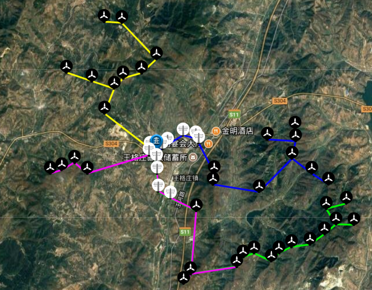
The optimized power line layout is displayed in GIS, and the legend is at the left bottom.
Expand the Layer Edit pane and click the Wire tab.
Click the Edit tab (default).
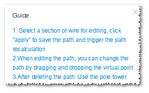
Expand the Guide pane to view the operation guide for editing wires.
Click the Edit button. The wire paths are editable now.
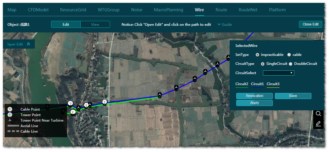
Edit the wires.
a.Click a section of the wire.
b.Click the Edit Path option on the wire. The control nodes appear.
c.Drag the control nodes to modify the direction and location of wire path.
Note
For double circuit, if you modify one of the wire path, the other one will not change. But after the calculation, the other wire path will be the same as the modified one.
Delete a wire.
a.Click a section of the wire.
b.Click the Delete Path option to delete this wire section.
Modify path properties.
a.Delete the path to be modified with the method introduced in Step 7.
Note
To modify the property of a path, you need to delete the original path, select the properties, and draw a new path. If the path to be modified is double-circuit, delete both the two circuits.
b.Select the erection form, circuit type, and circuit in the property panel at the right top of GIS.
c.Click one end of the cable/tower/substation deleted in Step a.
d.Click the pop-up Draw Path option. This end is taken as the start point for drawing a path.
e.Double-click to finish drawing.
f.Drag the control nodes of the drawn path to adjust its direction and location.
Note
The end point should be located at the other end of the cable/tower/substation deleted in Step a.
Note
If you want to draw a double-circuit path, select Double Circuit and assign the circuit in the property panel, and draw one wire path. After calculation, two circuits are displayed.
(Optional) Click the Save button to save all current modifications. If the wire paths are only saved but not re-calculated, when you refresh the browser and check the power line scheme again, a message pops up: The wire paths have been modified. Do you want to show them in edit mode?
You have two choices:
- Click OK to enter the edit page of saved wire paths.
- Click Cancel to show the wire paths after last calculation.
(Optional) Click the Revocation button. All your actions after the last wire optimization calculation are eliminated.
Click the Apply button. All the modifications are saved and the wire optimization task is submitted.
After the calculation, click the check box before the power line scheme object to view the wire paths after modification.
Note
It is recommended to click Apply only after you complete all modifications on the wire paths in order to reduce calculation times for time saving.
Note
All the actions will not be revocated after you click Apply.
Click the Close Edit button to finish wire path modification.
Double-click the power line object to open the Overview page.
The information displayed in the Overview page includes power line type, wire type, earth wire type, wire length, path length, split, wire safety coefficient, earth wire safety coefficient.
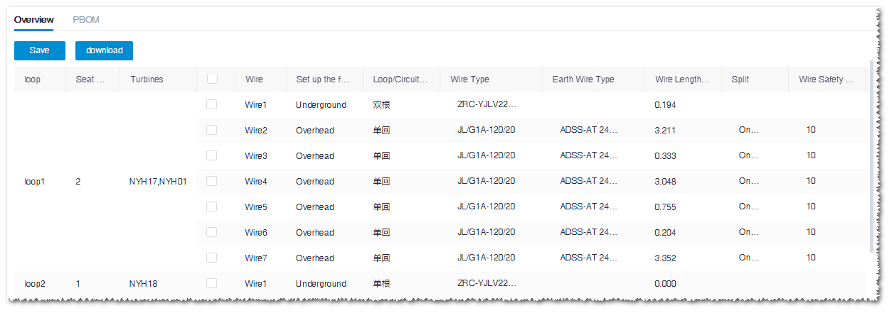
Click the Download button to export the overview table.
Optimizing Tower Layout
The operation of tower layout is only applicable in the cable or mixed wire optimization. It is performed only after the wire optimization calculation.
In the operation page, input the calculation type, weather condition, and parameters for calculation. The result is able to be checked after the calculation.
Configuring Parameters and Starting Calculation
Click the power line scheme object in the Project pane.
Click the expand icon 《 to open the operation pane.
Click the Operation tab.
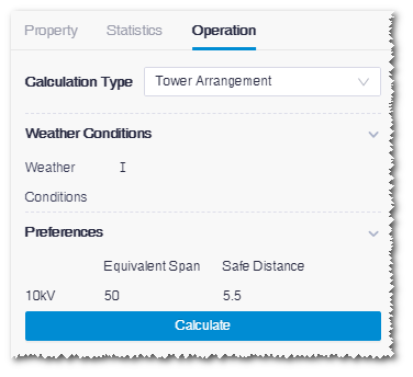
Select Tower Arrangement as calculation type.
Select the meteorological area number according to the project situation.
Six meteorological areas are listed: I, II, III, IV, V, VI, VII, VIII, and IX.
The temperature, wind speed, conductor ice thickness and earth wire ice thickness of each meteorological area are listed in the table.
Switch the area number to check the data values, and some data are editable.
Set up the parameters.
Three parameters are listed:
- Equivalent Span: The pre-defined range is 230 - 270m.
- Safe Distance: The pre-defined range is 5 - 14m, and the default value is 7m. Select the value in the drop-down menu.
- k Value: The pre-defined range 0.27E-03 - 0.33E-03.
Click Start Calculate to submit the calculation task.
Choose Tools Library > Task List to check the task status.
Checking Tower Layout Result
After the calculation is completed, click the check box before the power line scheme object. The power line layout is displayed in GIS, and the legend is at the left bottom of GIS.
Expand the Layer Edit panel at the left top of GIS.
Click the ArrangementTowerResult tab.
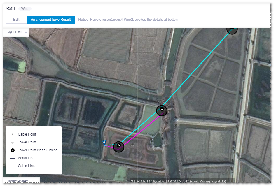
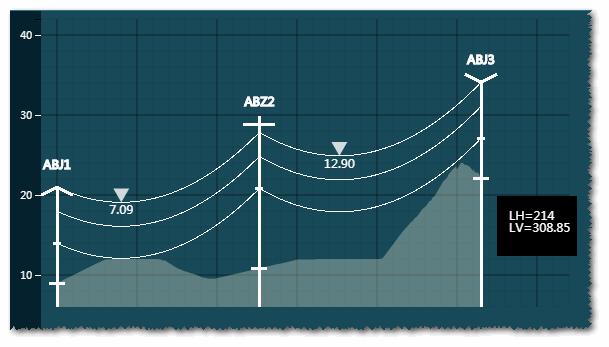
Click a wire in the layout. The tower layout in this wire is displayed. An example of Circuit2 - Wire2 is shown in the figure below:
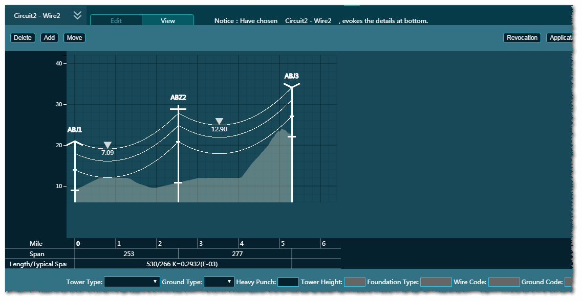
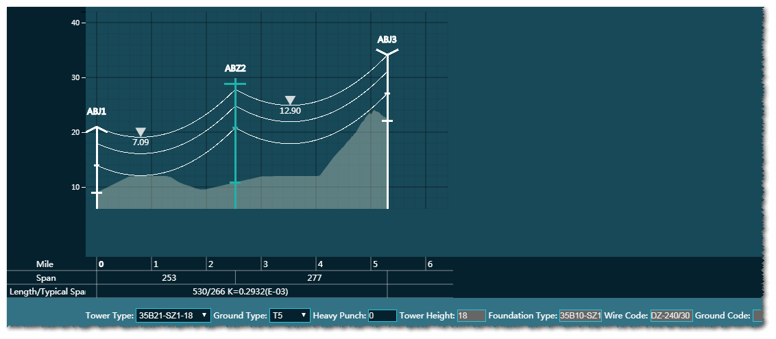
In the tower layout graph, the parameters of Mile, Span, and Length/Typical Span are displayed.
When the pointer hovers over the tower, a auto-tip appears showing the horizontal and vertical spans.
Click a tower. The tower type, ground type, heavy punch, tower height, foundation type, wire code, and ground code of this tower are displayed at the bottom line.
(Optional) Click the Delete, Add, and Move button to edit the towers.
a.Click the Delete button, select a tower, and click Apply to delete this tower.

b.Click the Add button, input the parameters at the bottom, and click in the graph. A new tower is added.
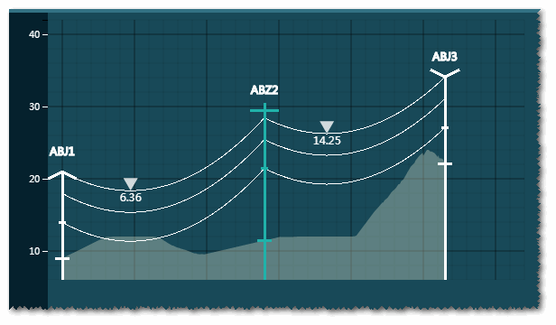
c.Click the Move button, select a tower, input the distance, and click the Left or Right button. The selected tower is moved by the defined distance.

The figure below shows the tower after moving.
Electric Check
This module checks the optimized scheme of wire and tower layout. The existing problems and possible causes are displayed, helping you adjust the design scheme.
Configuring Parameters and Starting Calculation
Click the power line scheme object in the Project pane.
Click the expand icon 《 to open the operation pane.
Click the Operation tab.
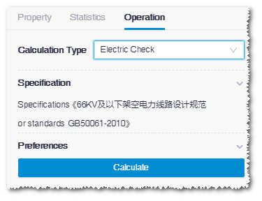
Select Electric Check as calculation type.
Select a specification. Currently, only one specification is available.
Set up the parameters. Each parameter is assigned with a default value. Use the default value or modify them as required.
Click Calculate. The calculation task is submitted.
Choose Tools Library > Task List to check the task status.
Viewing the Check Result
After the calculation, the results are displayed below the Start button.
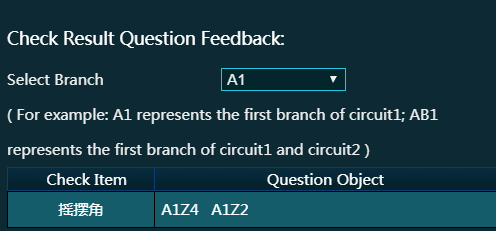
In the Check Result Question Feedback area, the problematic sections are listed in the table.
Note
If the electric check does not find any problem, it prompts that electric check has passed.
Select a branch to show its check result. A1 refers to the first branch of the loop of circuit1, and AB1 refers to the first branch of the double loop of circuit1 and circuit 2.
Click the name of the problematic section. The tower layout window opens.
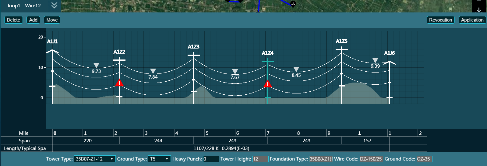
The red warning sign represents the problematic tower section.
Click the warning sign. The information window opens, showing the validated item, cause, and solution.
Adjust the tower layout according to the warning information.
Checking PBOM
Viewing PBOM
Double-click the power line scheme object to open the Overview page.
Click the PBOM tab.
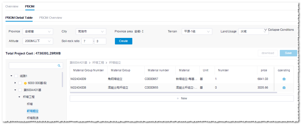
Expand the PBOM hierarchy at the left side.
Click the material group in the fourth level to show the materials and their quantity, unit, and price.
Editing PBOM
- Edit the number and price of the material.
- Click the Save button to save the modification.
Re-Generating PBOM
- Click the Create button to overwrite the current PBOM and restore the default values. A warning pops up.
- Click Save to save the modification.
Downloading PBOM
- Click the Download button to export the PBOM data as an Excel file in the default download directory of browser.
Generating CAD Drawing
Generating Drawings
Select the project in the Project pane.
Click the import/export button
 in the operation button area to open the Import/Export page.
Click the Export tab.
Select the category as Electric scheme in the menu.
Select the power line scheme to be exported in the drop-down menu.
Click the Submit button at the right side of the electric design drawings row. The coordinate window opens.
Select the coordinate, and click OK.
Choose Tools Library > Task List to open the Task List page.
Select Electric CAD in the drop-down menu to see the task status.
When the process reaches 100%, the calculation is completed.
Downloading Report
- Repeat Step 1-5 to open the Export page. The Download button is enabled.
- Click Download to download the CAD drawing.
- Check the downloaded file in the CAD viewer.