Route and Platform Design
This chapter introduces the configuration and calculation process of route and platform design, aiming to help you quickly get acquainted with wind farm platform design and route design.
The design procedure of wind farm route and platform is shown in the following figure:

Platform Design
This section introduces the operations related to platform design, including turbine model configuration, platform scheme creation, platform design, checking and editing the platform, checking platform PBOM, exporting platform scheme, and so on.
Setting up Turbine Library Parameters
The foundation of platform design is turbine library and turbine tower parameter configuration. In this section, the details of the configuration is introduced.
Before the platform design, ensure that a project has been created and the turbine model and WTG group are added into the project.
For details about adding a turbine model, refer to the section Importing Turbine Model .
For details about creating WTG group, refer to the section Importing Turbine Layout .
Click the turbine model object in the Project pane.
Click 《 at the right top of the interface to open the operation panel.
Click the Property tab.
Configure the parameters of turbine. The parameters to be configured for the turbine model are listed in the table below:
Configuration Object Type Parameter Name Turbine model Basic information Rotor diameter Rotor weight Blade Blade length Blade width Blade pivot distance Blade weight These values are acquired from the PLM turbine parameters.
Double-click the turbine model object and click the Component Configuration Management tab. For details of component group configuration, refer to the section Configuring Component Group . The parameters mandatory for component group applied in platform design are listed in the table below:
Configuration Object Type Parameter Name Component group Hub Hub length Hub width Nacelle Nacelle weight Nacelle length Nacelle width Nacelle height Configure tower parameters for the turbine model series. Refer to the section Configuring Applicable Tower . For the platform design, the bottom diameter of each tower section is mandatory. The bottom diameter is adopted from the external diameter of top end or bottom end of each tower section in the tower configuration parameters. If you fill in external diameter of both top end and bottom end, the bottom diameter is taken as the larger value of them.
Double click the wind farm layout object. The Overview page opens.
Configure the turbine model series, turbine model, component group, and length of each tower section.
Click Save to save the settings.
The turbine configuration for platform design is completed.
Adding a Platform Scheme
Platform scheme is designed for a specific project. To add a platform scheme to a project, you can create a new scheme or import an existing scheme.
Creating a Platform Scheme
Click the project name in the project pane.
Click the Import/Export button
 in the operation button area to open the Import/Export page.
Click the Create tab, and select Platform scheme as the category.
Select the Create radio button.
Input the value for Object Name.
Click Create.
A platform scheme object is added in the project tree.
Importing a Platform Scheme
Click the project name in the Project pane.
Click the Import/Export button
 in the operation button area to open the Import/Export page.
Click the Create tab, and select Platform scheme as the category.
Select the Import radio button.
Click the Upload button, and select a kml file with platform shape and elevation.
Input the value for Object Name.
Click Create.
A platform scheme object is added in the project tree.
Designing a Platform
For the created platform scheme, the following two operations are available: Platform and Hoisting Scheme for schemes without platform design or schemes requiring re-generation of platform design, and Platform Engineering Quantity for designed schemes needing re-calculation of engineering quantity due to elevation and shape adjustment.
Designing a Platform Scheme
Click the project name in the Project pane.
Click 《 to open the operation pane, and click the Operation tab.
Select Platform and Hoisting Scheme as the calculation type.
Select a WTG group with turbine model and tower parameter configuration, and set up the components.
a.Click the Components button to open the Components window.
b.Select turbines in the Select WTG row.
c.Set up the size of the required components
d.Select the optional components placed on the platform.
e.Click the Add button.
The details for the configured components are added as a group in the table at the bottom.
f.(Optional) If you need to reset the turbine components, click Delete to delete the existing configuration, and do the set up again.
g.Click OK to save all the groups.

Select the map for platform design in the Map area.
Input the values for Excavation Slope and Backfill Slope in the Design Parameters area.
The recommended range for these values are shown for your reference.
Select avoding area(s). The options available are areas saved as nature reserve area, basic farmland, eco red, and other areas not suitable for construction.
Note
You can select multiple avoiding areas, or buildings, water systems, existing roads, hardened areas as mentioned below. If no area is available or applicable, leave it empty.
Select constructions. The options available are Greenwich building database and customized building areas.
Select water area(s). The options available are Greenwich water area database and customized water areas.
Select roads and hardened areas. The options available are road network object(s) in the project and customized hardened areas.
Input the values for Excavation Price, Backfill Price, and Land Expropriation Price in the Cost Parameters area.
Click Calculate to start the calculation.
Calculating Engineering Quantity
- Click the project name in the Project pane.
- Click 《 to open the operation pane, and click the Operation tab.
- Select Platform Engineering Quantity as calculation type.
- Select the map for platform design in the Map area.
- Select buildings, water areas, roads and hardened areas. Refer to the above section for details.
- Click Start to start the calculation.
Viewing and Editing the Platform Properties
After the calculation, the platform design objects are generated under the platform scheme object according to the groups set in the operation pane. Check the platform properties and shapes, such as platform name, area, elevation, excavation quantity, backdrill quantity, cost, and so on. This section introduces how to check the platform properties.
Click to expand the platform design objects in the Project pane.
Click a platform design object.
Click 《 to open the operation pane, and click the Property tab.
(Optional) Click the Edit Property button to modify the name, description, display specification and elevation of the platform design object.
Click Save to save the settings.
Note
The platform engineering quantity is influenced by the elevation. If you modified the elevation value, re-do engineering quantity calculation as shown in the section Designing a Platform .
In the Property tab, check the results and parameters of individual platform design, including excavation quantity, platform elevation decrease amount, and so on.
Viewing the Platform
After the platform design is completed, modify the design parameters, export the overview table, and modify the project properties on the Overview page.
Double-click the platform scheme in the Project pane to open the Overview page. The table shows the engineering quantity including demolition cost, recommendation of hoist in each turbine location, etc.
Select one or more platform designs.
The columns with red * are the parameter columns. Click the cells under the column to edit the values.
After the modification, click Save.
Note
After the modification, you should re-do the quantity calculation. For details, refer to Designing a Platform .
Click Export to export an .xlsx file as the design overview table.
Click the PBOM tab, and set up the values of soil rock ratio, agrotype, rock type, and terrain for PBOM generation.
Editing and Drawing the Platform
After the platform design, the shapes of platforms are editable. If you edit their shapes, re-do the quantity calculation as shown in the section Designing a Platform .
Check a platform design object under the platform scheme, or click the platform design in GIS after you check the platform scheme in the Project pane. The corresponding platform is displayed in GIS.
Expannd the Layer Edit panel at the left top of GIS.
Click the Edit button.
(Optional) Click the control nodes to delete them; drag the control nodes to add nodes and modify the platform shape.
After the modification is done, click the Save button to save the changes, or click Revocation to give up the settings.
Check Show ornaments, Show cost area, or Show warning to show hoist method, hoister assembling space, etc.
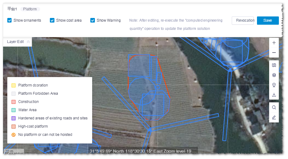
Other than editing the existing platform object, you can draw a platform and associate it to a platform scheme.
a.Draw a polygon in GIS. For details, refer to the section Drawing a Polygon .
b.Click the project name, and click the Save button in the tools menu.
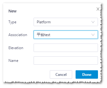
c.In the pop-up window, select Platform as type, input the name and elevation, and select the associated scheme in the drop-down menu.
d.Click the Done button.
Checking Platform PBOM
After the platform scheme is designed, the PBOM details are provided in the PBOM page of platform overview.
Double-click the platform scheme object in the Project pane. The Platform page is opened.
Click the PBOM tab to check the PBOM parameters.
Expand the hierarchy of PBOM at the left side.
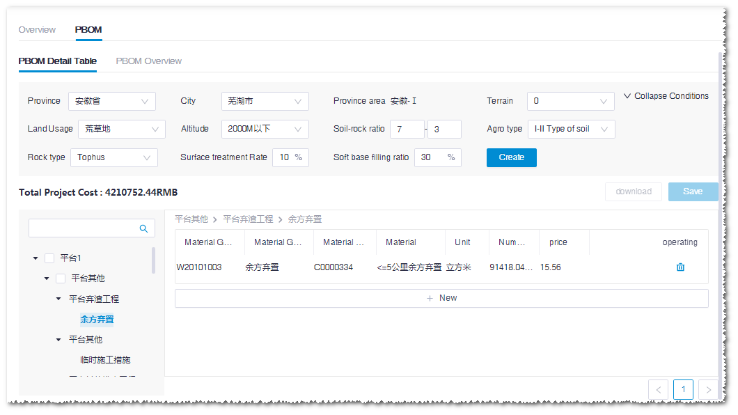
Add materials in the material tree.
a.Select the material group No. and material No.
b.Input the engineering quantity.
c.Input the price.
d.Click the + icon to add a material item.
e.Click Save at the left top of this page to save the settings.
Edit the quantity and price.
a.Double-click the cells under the Number and Price column to edit their values.
b.Click Save at the left top of this page to save the settings.
Delete the material.
a.Click the delete icon
 at the right end of an item to delete the respective material.
b.Click Save at the right top of this page to save the settings.
Exporting Platform Scheme
- Click the project name in the Project pane.
- Click the Import/Export button
 in the operation button area to open the Import/Export page.
 - Click the Export tab.
- Select Platform scheme in the menu.
- Select a platform scheme in the Platform scheme drop-down menu.
- Click the Download button in the desired file type row. The corresponding file is downloaded. The file formats available are kml and Microsoft Word. The figure of each turbine location need to be screenshot by yourself.
Existing Road Network
All the road networks in China are collected in the Greenwich platform. In GIS, you can check the road networks and download them. The road network data are not real-time data, but they are maintained and updated regularly by Greenwich.
Checking Nationwide Road Networks
In GIS, check the road networks in different levels in China.
Click the data layer icon
 in toolbar menu to open the data layer list.
Expand the Road Network list.
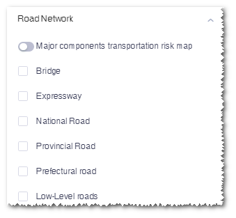
Select the road levels to see the corresponding road networks within China in GIS.For more details of map layers, refer to the section Data Layers .
Importing Road Network
The outsourcing road network files in the kml format is compatible in Greenwich, and can be imported for scheme design.
- Click the project name in the Project pane.
- Click the Import/Export button
 in the operation button area to open the Import/Export page.
 - Click the Create tab, and select Road network in the menu.
- Browse to select a line file in the kml format.
- Select the road level and input the object name.
- Click Create to import the road network.
Downloading Road Network
For route design, substation design, .etc, the existing road network can be downloaded as an object in the project.
Click a project name in the Project pane.
Click the download icon
 in the toolbar menu.
Select the region, type, and road level.
Click the Download button to download the road network of the select region as an object in the project.

Editing and Drawing the Road Network
After you download the road network, you can edit it by adjusting the route and deleting the route and modify its properties. In addition, you can manually draw a road network and save it in the project.
Click a road network object in the Project pane. It is displayed in GIS.
Expand the Layer Edit panel at the left top of GIS.

Edit the route property.
a.Click Edit Property.
b.Click the Edit button.
c.Click a route to be modified. The Edit Route Net window pops up.
d.Select road level and surface property, and input road width.
Note
If you need to edit more than one route, select the routes, and perform Step a to edit their properties. When any one of their property is the same, the corresponding value of the property is displayed. If their property is different, the value of the corresponding property is displayed as Multiple.
e.(Optional) Click Clear to deselect all routes, and you can select the route again.
f.Click Confirm to close the window.
g.Click the Save button on the layer edit pane to save all changes.
Edit the route.
a.Click Edit Line.
b.Click the Edit button.
c.Click a road to make it editable.
d.Drag or add the control nodes to change the shape of road.
e.(Optional) Click Delete road to delete the road under the editing status.
f.(Optional) Click Revocation to cancel all changes.
g.Click Save to save the changes.
In GIS, draw lines to add road network.
a.Click a project name in the Project pane.
b.Click the draw and measure icon
 in the toolbar menu.
c.Click Line.
d.Draw lines in GIS. For details, refer to the section Drawing a Line .
e.Click the Save button. The following window opens.
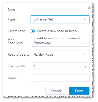
f.Select type as Entrance Net.
g.Select the road creation type.
- Create a new road network: Create a new road network object in the project
- Add to existing road network: Add the created route to a existing road network, and you need to select the respective road network
h.Select the road level and property and input the name.
i.Click the Done button to complete the drawing.
Exporting Road Network
The road network in Greenwich can be exported in the specified format.
- Click a project name in the Project pane.
- Click the Import/Export button
 in the operation button area to open the Import/Export page.
 - Click the Export tab.
- Select Road network in the menu.
- Select the road network to be exported in the Road network drop-down menu.
- Select the format of the exported file, and click the Download button at its right side. The desired file is downloaded to the default download directory of the browser.
Route Network Major Component Transportation Cost Evaluation
The road network major component transportation cost evaluation aims to calculate the reconstruction and expansion cost of route network on different routes with specific transport vehicle, major component size, and cost area.
Configuring for the Calculation
This section introduces how to configure parameters applied in route network major component transportation cost calculation.
Because the size of major component is influential in the route network major component transportation cost calculation, before configuring for the calculation, set up the turbine model and tower length of the wind farm. For details, refer to the section Configuring Turbine Property .
Click the road network object under the project tree. For more information about how to draw and import road network, refer to the section Existing Road Network .
Click the expand icon 《 at the right top of GIS to open the operation pane.
Click the Operation tab.
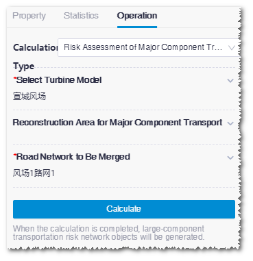
Expand the Select Turbine Model area, select a wind farm, and click Done. The options in the list are all wind farms in the project, but only wind farms with configuration of turbine model and tower length can be selected.
Expand the Reconstruction Area for Major Component area.
Note
If no construction area is there within the selected wind farm, skip Step 5-7.
Select reconstruction area(s). Reconstruction area is classified into two categories:
Data Base consists of the buildings and river system database of the system. Their costs are defined by default. If you want to modify the cost, click the check box of the corresponding database and modify its cost value.
Custom Avoding Zone lists areas customized and defined as protection zone, minerals, earthquake site, etc. For details, refer to the section Drawing a Polygon .
The Type column shows the property of this area. To modify or input he value of Cost, click the check box of the area and input the value manually.
Click Done to save all changes.
Expand the Road Network to Be Merged area.
Select road network. All the road network in the project are listed. The road network operated in this section is listed at the top and selected by default. Select other road network object(s) to merge them.
(Optional) Click the drag the road network object (other than the one operated in this section) to change its order.
Click Done to save all changes.
Click Calculate to submit the routenet calculation task.
Choose Tools Library > Task List.
Select RouteNet Calculate in the task type list to check the task status. When the progress reaches 100%, the calculation is completed.
Click the project name in the project pane, and click the refresh button
 . The newly generated route network object is displayed in the project tree.
Checking Calculation Result
This section introduces how to check and edit the road network properties.
Click the checkbox of the road network major component object in the project tree.
View the route distribution in GIS. The reconstruction cost of major component transportation is demonstrated with different colors on the routenet.
Click Layer Edit in GIS to open the layer edit pane.
Click the Edit button.
Click a route to edit its property. The selected route is displayed bold and the Edit Route Net window pops up.
Modify the cost and quantity of the route net properties and the cost is updated automatically.
Select road level and surface property, and input road width.
Note
If you need to edit more than one route, select the routes, and perform Step 7-8 to edit their properties. When any one of their property is the same, the corresponding value of the property is displayed. If their property is different, the value of the corresponding property is displayed as Multiple.
(Optional) Click Clear to deselect all routes, and you can select the route again.
Click OK to close the window.
Click the Save button on the layer edit pane to save all changes.
Route Design
This section introduces the operations related to route design, including creating route scheme, drawing start point and necessary point, designing route, optimizing route engineering quantity, generating PBOM, and downloading route drawing and scheme.
Adding a Route Scheme
Route scheme is designed for a specific project. Before adding a route scheme, create a project, and create a new scheme or import an existing scheme.
Creating a New Route Scheme
Click the project name in the Project pane.
Click the Import/Export button
 in the operation button area to open the Import/Export page.
Click the Create tab, and select Route scheme as the category.
Select the Create radio button.
Input the value for Object Name.
Click Create.
A route scheme object is added in the project tree.
Importing a Route Scheme
Click the project name in the project pane.
Click the Import/Export button
 in the operation button area to open the Import/Export page.
Click the Create tab, and select Route scheme as the category.
Select the Import radio button.
Click the Upload button, and select a kml file with line information.
Input the value for Object Name.
Click Create.
A route scheme object is added in the project tree.
Drawing Start Point and Necessary Point
In the route design process, you can manually draw points in GIS as route start point and necessary point.
Click the project in the Project pane.
Click the draw and measure icon
 in the toolbar menu, choose Draw, and click Point.
Click in GIS. The point is marked.
Click the Save button. The New window opens.
Select the type as Route Start Point or Route Necessity Pointer.
Input the point name.
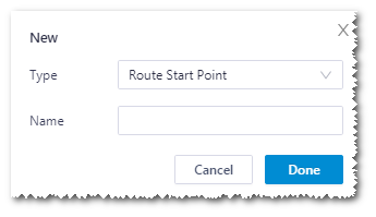
Click Done to add a point object in the project tree.
Select the newly created start point or necessary point in Project tree, and open the operation pane.
Click the Property tab, and modify the name, description and coordinate of the point.
Click Save to save the changes.
Designing the Route
Route scheme design is consisted of two phases. The first one is route design; the second one is optimization for cross section, profile section, and engineering quantity calculation based on the designed route. This section introduces the route design process.
Click the created route scheme object in the Project pane.
Click 《 at the right top of the interface to open the operation pane.
Click the Operation tab.
Select Route Path Design as calculation type.
(Required) Select the WTG group layout in the list.
(Required) Select the map for route design.
(Required) Select the start point. Two categories of start point are available:
- Database: The road network within the planned area is downloaded automatically as the start point of route design
- Customization: Select the drawn start point, or the downloaded or drawn road network. For details on start point drawing, refer to Drawing Start Point and Necessary Point . For more information on existing road network, refer to Existing Road Network .
(Optional) Select the road for reconstruction. Options listed are road network objects calculated by route network major component risk evaluation. For more details, refer to the section Route Network Major Component Transportation Cost Evaluation .
(Required) Select the planned area for route design.
The route design is permitted only in the selected area.
(Optional) Select the prohibited area
Farm land, mineral area, buildings, protection areas, etc. are prohibited areas for route design.
(Optional) Select the necessary point of route. If there is point that must be passed in the wind farm, you should select this point as the necessary point.
(Required) Input the cost parameters.
Click Calculate. This calculation is submitted to the task list.
Choose Tools Library > Task List.
On the Task List page, select the time range of task submission, select Road Path Design as the task type, and click Check to show the task status of the route design.
Optimizing Route Engineering Quantity
For existing route, such as designed route and imported road network, you can optimize its engineering quantity by calculation.
Click the route scheme in the Project pane.
Click the expand icon 《 to open the operation pane.
Click the Operation tab.
Select Optimization as calculation type.
Select calculation control. The calculation control options are Optimize all and Optimize profile and cross-sectional. The Optimize all mode modifies the route design form some minor adjustments, and Optimize profile and cross-sectional does note adjust the route design.
Select a designed platform scheme. Platform scheme is required for the engineering quantity calculation, so you should select a platform scheme before the calculation.
Select a WTG group. The WTG group selected should be configured with the blade length parameter in the property pane of the turbine model. For details, refer to Setting up Turbine Library Parameters .
Select the map for calculation.
Select the planned area for engineering quantity optimization.
The engineering quantity optimization is permitted only in the selected area.
Select the prohibited area.
Farm land, mineral area, buildings, protection areas, etc. are prohibited areas for route design.
Select transport methods.
Click Calculate. This calculation is submitted to the task list.
Choose Tools Library > Task List.
On the Task List page, select the time range of task submission, select Road quantity as the task type, and click Check to show the task status of the engineering quantity optimization.
Viewing the Route
After the route design is completed, modify the design parameters on the Overview page.
Double-click the route scheme in the Project pane to open the Overview page.
Select one or more route designs. The columns with red * are the parameter columns. Click the cells under the column to edit the values.
After the modification, click Save.
Note
After the modification, you should re-do the quantity optimization. For details, refer to Optimizing Route Engineering Quantity .
Click Export to export an .xlsx file as the design overview table.
Click the PBOM tab, and set up the values of soil rock ratio, agrotype, rock type, and terrain for PBOM generation.
Editing and Drawing the Route
After the route design, the shapes of routes are editable. If you edit their shapes, re-do the quantity optimization in the Optimize profile and cross-sectional mode as shown in the section Optimizing Route Engineering Quantity .
Check a route design object under the route scheme, or click the route design in GIS after you check the route scheme in the Project pane. The corresponding route is displayed in GIS.
Expand the Layer Edit panel at the left top of GIS.
For route scheme after quantity optimization, check Smooth Curve and Roadside Line.
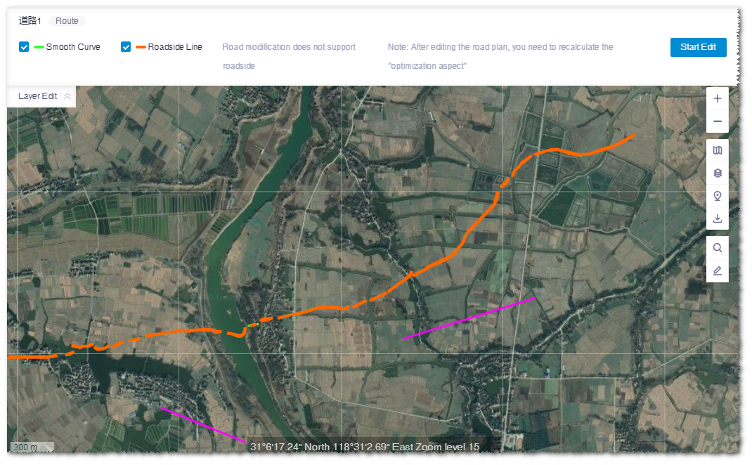
Click the Start Edit button.
Click the control nodes to delete them; drag the control nodes to add nodes and modify the route shape.
After the modification is done, click the Save button to save the changes, or click Revocation to give up the settings.
Other than editing the existing route object, you can draw a route and associate it to a route scheme.
a.Draw a line in GIS. For details, refer to the section Drawing a Line .
b.Click the project name, and click the Save button in the Layer Edit panel. The New window pops up.
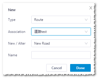
c.In the pop-up window, select Route as type, select the creation type and associated scheme, and input the name.
Note
If you select Entrance Road as road type, you need to select the surface type and width of original road.
d.Click the Done button.
Checking Route Profile and Cross Sections
After the engineering quantity optimization is completed, check the route profile section and cross section design.
Click the route scheme after engineering quantity optimization in the Project pane.

Click the expand button at the left bottom of the interface to display the profile and cross section page.
Switch the tabs to show the profile and cross section design.

Checking Route PBOM
After the engineering quantity optimization is completed, the PBOM details are provided in the PBOM page of route overview.
Double-click the route scheme object in the Project pane. The Route page is opened.
Click the PBOM tab to check the PBOM parameters.
Expand the hierarchy of PBOM at the left side.
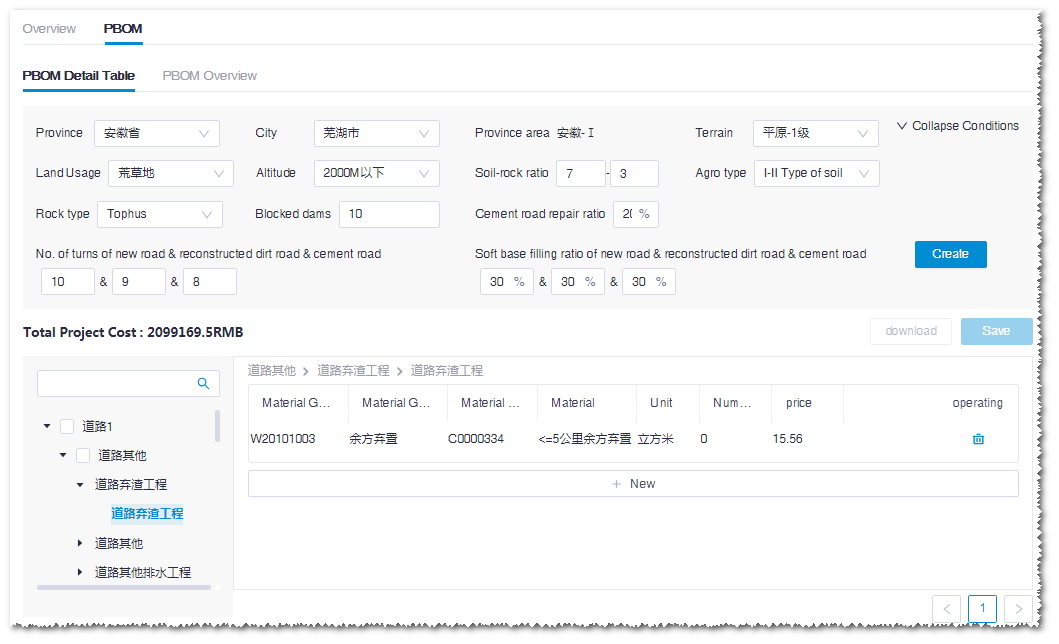
Add materials in the material tree.
a.Select the material group No. and material No..
b.Input the engineering quantity.
c.Input the price.
d.Click the + icon to add a material item.
e.Click Save at the left top of this page to save the settings.
Edit the quantity and price.
a.Double-click the cells under the Number and Price column to edit their values.
b.Click Save at the right top of this page to save the settings.
Delete the material.
a.Click the delete icon
 at the right end of an item to delete the respective material.
b.Click Save at the left top of this page to save the settings.
Generating Route Drawing
After the engineering quantity optimization is completed, you are enabled to generate the CAD drawing of the surface, profile, and cross sections of the route and platform design.
Select the project in the Project pane.
Click the import/export button
 in the operation button area to open the Import/Export page.
Click the Export tab.
Select the category as Route scheme, and select the route scheme to be exported in the drop-down menu.
Click the Submit button at the right side of the route design drawing row.
Note
The drawing is only downloadable after submitting calculation.
Input the coordinate information in the pop-up window.
You must input the projection, zone and datum values according to the project requirements.
Click OK to submit the calculation task.
Choose Tools Library > Task List to open the Task List page.
Define the task submission range, and select task type as CAD Map.
Click Check to display the task status of CAD generation.
After the generation is completed, repeat Step 1-4, and click the Download button at the right side of the route design drawing row. The route design drawing is downloaded into the default download directory of the browser.
Exporting Route Scheme
This section introduces how to export route scheme as a kml file.
- Click the project name in the Project pane.
- Click the Import/Export button
 in the operation button area to open the Import/Export page.
 - Click the Export tab.
- Select Route scheme in the menu.
- Select a route scheme in the Route scheme drop-down menu.
- Click the Download button in the desired file type row. The corresponding file is downloaded.