Database
Database includes the referential data and models for Greenwich.
Device Library
Device library is consisted of Turbine Library,Transport Library,PV Module and Inverter Library.
Turbine Library
In turbine library, you can see various turbine models. Correspondingly, the power curve, noise curve, tower, foundation load, and other information of the turbine model are displayed for viewing and setting up the turbine model parameters. You can accordingly select the turbine model applicable to the project.
Turbine models stored in the turbine library are classified into two categories as shown in the figure below:
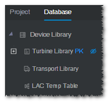
- Public Library: Third-party turbine models
- Envision: Turbine models produced by Envision
This section introduces the turbine library configuration and application through two dimensions, that is turbine model series and turbine model. Additionally, this section introduces some basic operations on the turbine library broadcasts. The details are listed below:
Turbine model series
- Adding a turbine model series
- Checking the turbine model series property
- Configuring turbine model series
Turbine model
- Adding a turbine model
- Checking the turbine model property
- Configuring operation mode
- Configuring component group
- Configuring foundation load
- Turbine configuration PK
Turbine version broadcasts
- Manage turbine version broadcasts

- Cancel turbine version broadcasts

- Check turbine version broadcasts
Note
The main concern of this section are operation and configuration in the turbine library. The objects as turbine model series and turbine model set up here can be reused in multiple projects. For an individual project, you can also add and configure turbine model, turbine model series, etc., but these configurations can be applied only in the corresponding project. For details of configuring turbine model in the project, refer to the section Importing Turbine Mode.
Turbine Model Series
Turbine model is a general term for a group of turbine models. The configuration of turbine model series consists of adding turbine model series, checking turbine model series property, checking embedded turbine models, and editing applicable tower.
Adding Turbine Model Series
To create a turbine model series object under a turbine library domain or folder, perform the following steps:
Choose Database > Device Library > Turbine Library.
Tip
Click the Hide Empty Folder icon
 to hide the empty folders in turbine library.
Click a Domain name or a folder.
Click the Create turbine model series icon
 in the operation button pane.
The Create turbine model series page opens.
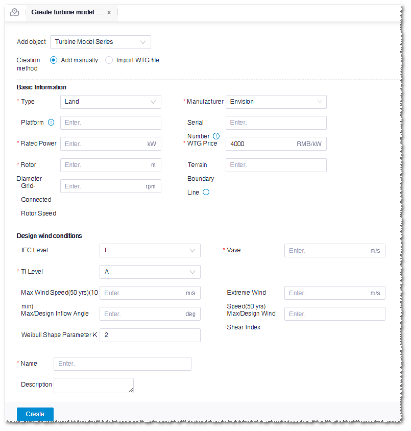
Select the creation mode as Add manually.
Note
If you have any WTG file, select Import WTG file to create a turbine model series.
Input the parameters in the basic information, design wind conditions, and name fields. Among them, the items marked with a red * are mandatory.
Click the Create button. A turbine model series object is created under the selected Domain or folder.
Note
The icon of turbine model series is

Checking Turbine Model Series Property
The turbine model series property consists of three categories, that is, basic information, design wind conditions, and environmental parameters. You can check and modify them in the Property pane.
Click the turbine model series object in turbine library.
Click the expand icon 《 at the right top of the interface to open the property pane.
Click the Property tab. The property parameters include three categories, that is, basic information, design wind conditions, and environmental parameters.
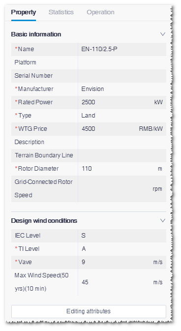
The parameters with a red * are mandatory.
Click the Editing attributes button.
Input or edit the property parameters. In the Environmental parameters module, you can add the applicable temperature parameters. The types are normal temperature, standard, and low temperature, which define the survival temperature and operation temperature of the turbine model series in various environment.
Click the Save button to save the settings.
Configuring Turbine Model Series
The turbine model series configuration consists of two modules, that is, turbine model overview and applicable tower configuration.
Double-click the turbine model series object in turbine library. The corresponding configuration page opens.
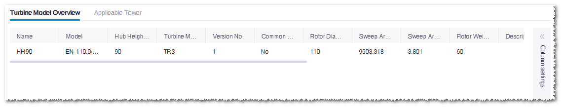
Checking Turbine Model Overview
Check the turbine model(s) under the turbine model series on the Turbine model overview tab.
Note
If the current turbine model series is newly created, no turbine model is available on this page. You need to adding a turbine model series.
Click Column settings at the right side of the page to open the parameter options.
Select the desired parameters in the menu list to adjust the items in the table.
Configuring Applicable Tower
On the Applicable Tower tab, check the applicable tower(s) of the turbine model series and the detailed parameters.
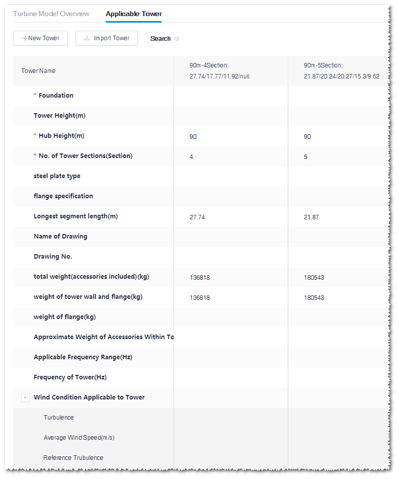
Click Search to expand the search conditions.
Select hub height, No. of tower sections, and/or foundation form, and click the Search button. The towers are listed according to the search conditions.
Note
If you set up the search conditions, when the search condition pane is collapsed, a red dot is displayed beside Search.
(Optional) Add a tower.
a.Click the New Tower button to add a blank tower record in the tower list.
b.Select or input the tower parameters, including foundation form, No. of tower sections, natural vibration period, flange, etc.
Note
Among these parameters, the foundation form, hub height, No. of tower sections, and the length and height of each section are mandatory.
After the parameters are configured, the tower name is displayed automatically as hub height-No. of sections: length of each section.
- Click the Save button to save the tower configurations.
(Optional) Import a tower.
a.Click the Import Tower button.
b.Click Download template in the pop-up Import Tower window. The tower template file is downloaded to the default download directory of the browser.
c.Input the tower parameters in the downloaded .xlsx file and save it.
d.Click the Upload button in the Import Tower window to upload the tower parameter file.
e.Click OK.
f.Click the Save button to save the tower configuration.
Note
While saving the tower configuration, if the load envelope information of standard tower is found according to the index parameters (name of bidding drawing, bidding drawing No., frequency, extreme wind speed), the Load Envelope field is displayed as Yes. If not, it is displayed as No.
(Optional) Modify the tower parameters.
a.Double-click the tower parameter cell. The parameters become editable.
b.Modify the parameters.
Note
The Load Envelope field is not editable.
c.Click the Save button to save the tower configuration.
(Optional) Delete tower.
a.Hover the cursor over the tower name. The delete icon
 displays beside the name.
b.Click the delete icon. The confirmation dialogue box pops up.
c.Click OK. The corresponding tower is deleted.
Turbine Model
Turbine model is a composition of the detailed parameters and configurations of a single turbine model. It consists of three categories of parameters, that is, operation mode, component group, and foundation load.
This section covers the instruction to add a turbine model, check turbine model property, configure operation mode, configure component group, configure foundation load, and turbine configuration PK.
Adding Turbine Model
Choose Database > Device Library > Turbine Library.
Tip
Click the Hide Empty Folder icon
to hide the empty folders in turbine library.Click a turbine model series object.
Click the Create turbine model icon
in the operation button pane.The Create turbine type config page opens.
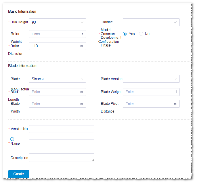
Input the parameters in the basic information, blade information, version No., and name fields. Among them, the items marked with a red * are mandatory.
Note
Only one common turbine model is permitted for a turbine model series at a hub height.
Click the Create button. A turbine model object is created under the selected turbine model series.
Note
The icon of turbine model is

Checking Turbine Mode Property
The turbine model property consists of two categories, that is, basic information and blade. You can check and modify them in the Property pane.
Click the turbine model object in turbine library.
Click the expand icon《 at the right top of the interface to open the property pane.
Click the Property tab. The property parameters include two categories, that is, basic information and blade.
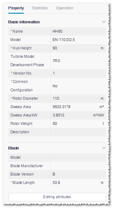
The parameters with a red * are mandatory.
Click the Editing attributes button.
Input or edit the property parameters.
Click the Save button to save the settings.
Configuring Operation Mode
This module defines the operation mode of the turbine model, including power curve and noise curve.
- Double-click the turbine model object in turbine library. The corresponding configuration page opens.
- Click the Operation mode overview tab to check the operation mode menu list.
Adding Operation Mode
Click Add operation mode to open the operation mode setup page.
Note
To modify the existing operation mode, click Edit at the right part of the operation mode record to open the setup page. The settings are the same as that of adding a new operation mode.
The operation mode setup page consists of three sections, that is, basic settings, power curve, and noise curve. The configuration is demonstrated as in the following sections:
Basic Settings
Input the parameters in the Basic Settings area.
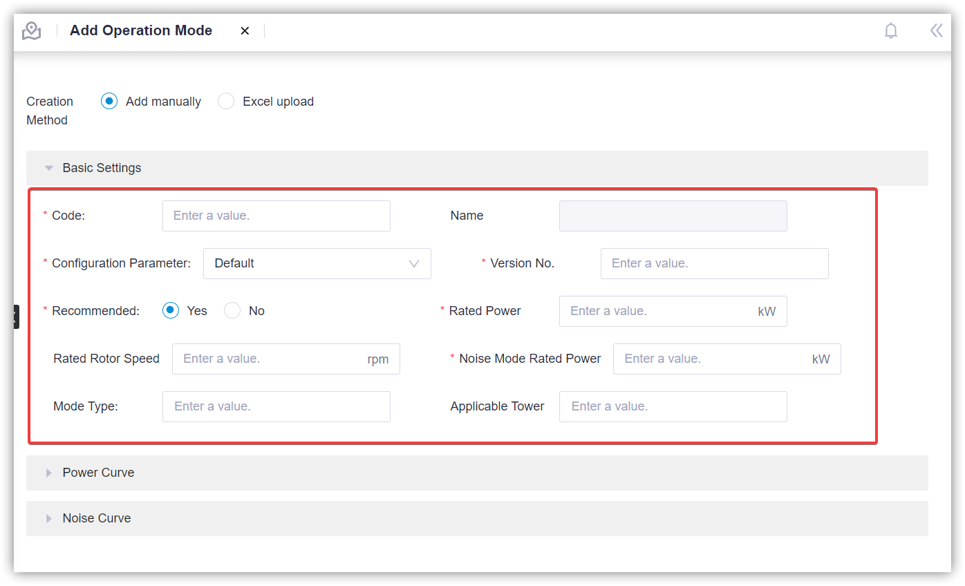
The items marked with a red * are mandatory. Pay attention to the following parameters:
Table: Operation Mode Parameters
| Parameter Name | Option | Description |
|---|---|---|
| Configuration parameter | Default | Standard blade form |
| Serrations | Blade form with serrations | |
| Mode type | Default | Turbine operation mode tags. You can select more than one of them. |
| Boosting | ||
| Noise | ||
| Derating | ||
| Applicable tower | All applicable towers in the turbine model series to which this turbine mode belongs | You can select more than one towers. |
Note
For a turbine model, only one common operation mode is permitted.
Power Curve
Expand the Power curve area.
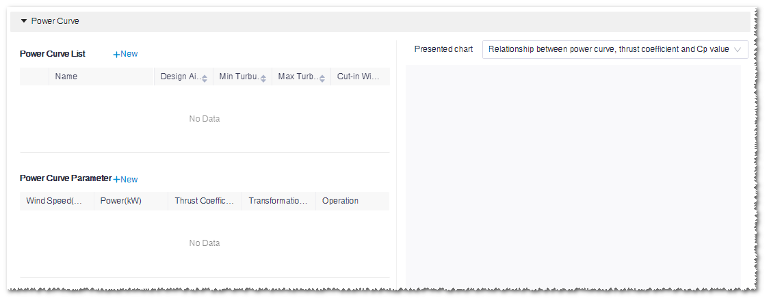
Click New at the right top of Power curve list. The New power curve window opens.
Select Manually added. The items marked with a red * are mandatory.
Note
If you select Import, click Template download, modify in the template file, and upload it.
Input the power curve parameters.
Click OK. A new power curve record is added in Power curve list.
Input wind speed, power, and thrust coefficient in the Power curve parameter table.
Wind speed: The wind speed of power curve
Power: The output power at the respective wind speed
Thrust coefficient: The thrust coefficient at the respective wind speed
Note
To edit the existing power curve parameter, double-click the item in the Power curve parameter table.
(Optional) Click New at the right top of the Power curve parameter table. A wind speed record is added at the bottom of the table.
(Optional) Click the delete icon
 in the Operation column of the Power curve list or Power curve parameter table to delete the corresponding power curve or wind speed record.
Select power curve(s) in the Power curve list and check the power curve graphs at the right side of the page.
- Relationship between power curve, thrust coefficient and Cp value: show the relationship among power curve, thrust coefficient, and Cp value
- Power performance rendering: show power production performance by the k value of Weibull function and full-load hours
- Comparison chart of power generation performance at a specific K value: show power production performance in a specific k value
Note
In the Power performance rendering mode, no more than two curves can be selected.
Note
In the Relationship between power curve, thrust coefficient and Cp value view, if you select two or more power curves, only the power curves are displayed without the Ct and Cp graphs.
Noise Curve
Expand the Noise curve area.
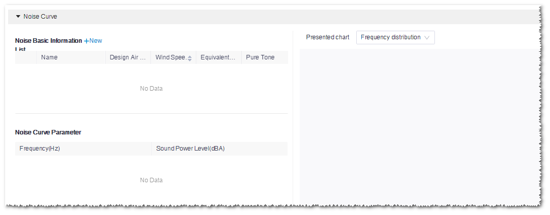
Click New at the right top of Noise basic information list to open the New noise curve window.
Select Manually added.
Input the noise curve parameters. Type, wind speed at hub height, and design air density are mandatory items. Three options are available for noise curve, that is, Single frequency, One third octave, and Octave.
- Single frequency: The sound power level with a specified single frequency
- One third octave: The sound power level displayed by frequencies divided into three sections
- Octave: The sound power level displayed by frequencies
Note
If you select Import, click Template download, modify in the template file, and upload it.
Click OK. A new noise curve record is added in the Noise basic information list.
(Optional) Double-click in Noise basic information list to edit the noise curve information.
Select a noise curve. The corresponding parameters are displayed in the Noise curve parameter table.
Input the Sound Power Level in the Noise curve parameter table.
Note
If there is value as power curve level, double-click the cell to modify it.
Note
When the noise curve type is One third octave, click the switch button at the right top of the Noise curve parameter table to switch between the Octave mode and 1/3-octave mode.
Saving Operation Mode
Click the Create button in the operation mode setup page. A new operation mode is added in the menu list.
Note
If you edited the existing operation mode, click the Save button after you complete the configuration. The original one is accordingly refreshed.
- After you configure the Basic settings parameters, the operation mode is available to be created.
- After you add a new operation mode, double-click the turbine model to open the configuration page and the newly added operation mode is displayed.
- After the parameters in the basic settings, power curve, or noise curve sections are set, Configured is marked in the correspond section.
Checking Operation Mode
Select operation mode in the Operation mode list on the Operation mode overview page.
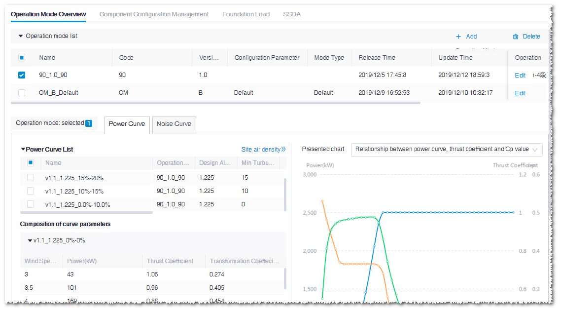
Click the Power or Noise tab to check the curve details.
Note
If no power curve or noise curve is available for the operation mode, a tip is displayed on the interface. Click Edit to redirect to the corresponding power curve or noise curve setup page.
Checking the Site Air Density Conversion
By default, the power curve displayed is in the standard air density, that is, 1.225kg/m3. This condition is not suitable for all wind farms. Considering the actual air density, the standard power curve should be transformed into actual power curve. In the AEP calculation, the actual power curve is adopted.
- Click Site air density at the right top of the power curve or noise curve table to open the Site air density page.
- Select a power curve. The options are power curves selected in Power curve list of the current operation mode.
- Input Site air density.
- Click the Conversion button.
- The table at the left side shows the power before and after conversion at various wind speeds
- The graph at the right side shows the two power curves before and after the conversion
- When you finish checking the conversion, click back
 at the left top to return to the Operation mode overview page.
Configuring Component Group
This page defines the component group of turbine model.
Double-click the turbine model object in turbine library. The corresponding configuration page opens.
Click the Component configuration management tab.
Click the quick view options to view the relative configuration parameters. The available options are All, Access plan, Platform and hosting scheme, Foundation check, Load adaptability evaluation, EBA, and Electric single-line graph.
Click the parameters corresponding to the selected quick view option to edit them.
Note
The value in the Status column indicates whether the component group can be applied in the applicability analysis calculation. Active stands for calculable and Inactive stands for incalculable.
Click Column settings to expand the component group parameter option list.
Select the parameter items to customize the items in the table.
Add a new component group.
a.Click the New component group button. A new row of blank component group record is added in the table.
b.Input the name and set up other parameters.
Click in the table. The parameters become editable. Edit them if needed.
- (Optional) Click the delete icon at the right side of the component group to delete the respective component
group.
- (Optional) Click the delete icon
Click the Save button to save all settings.
Configuring Foundation Load
This page defines the load configuration of turbine model.
Double-click the turbine model object in turbine library. The corresponding configuration page opens.
Click the Foundation Load tab.
Click Template download to download the template file into the default directory of the browser.
Open the template file, modify the parameter values, and save the file.
Return to the Foundation Load page, click the Import button, and load the modified template file. The Set up earthquake load parameter wind pops up.
Set up the earthquake level, acceleration, characteristic period of response spectrum, and extreme wind speed.
Click the Start importing button. The values in the file are displayed in the load table.
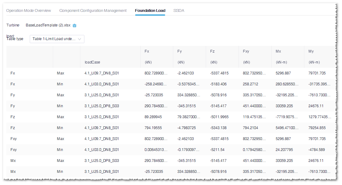
Each sheet in the file is correspondent to an option in the Table type list.
(Optional) Click the delete icon
at the right side of the file name in the Turbine load field to delete the displayed load data.
Turbine Configuration PK
The turbine model PK function helps you evaluate key factors in wind farms, such as full-load hours, to quickly choose the optimal turbine model for your wind farm.
Click the Turbine configuration PK icon at the right side of Turbine Library to open the Turbine configuration PK page. Two tabs, Turbine Model PK and Results, are consisted on this page.
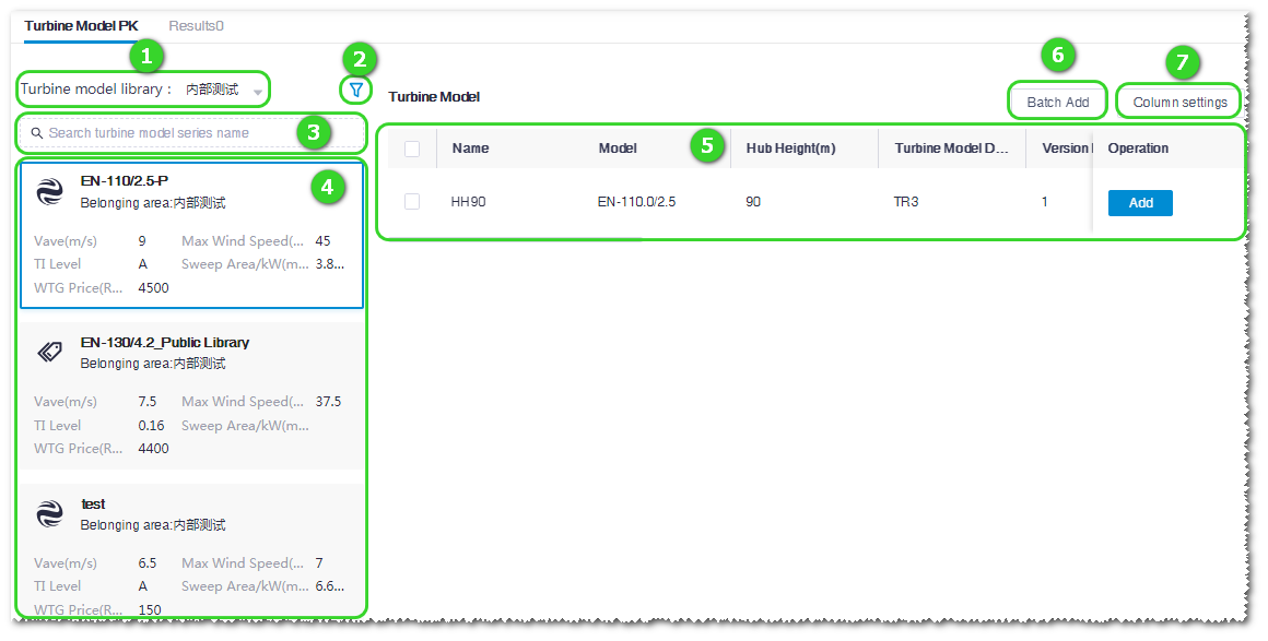
Turbine Model PK
On the Turbine Model PK tab, select turbine model series and add the turbine models to the result page.
| No. | Name | Description |
|---|---|---|
| ① | Turbine library hierarchy | Expand this menu and select a domain. All turbine model series under this domain are displayed in Area ④. |
| ② | Turbine series filter conditions | Click this icon to open the Turbine Model Series Filtration window, select filter conditions, and click Confirm. All turbine model series in accord with the selected filters are displayed in Area ④. 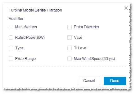
|
| ③ | Turbine model series search | Input the turbine model series name in the search box. All turbine model series with the searched name are displayed in Area ④. Fuzzy search is supported. |
| ④ | Turbine model series list | All turbine model series in accord to the filters and conditions defined in ①②③ are listed. Each turbine model series tag shows its basic information. Click a turbine model series. Its turbine model information is shown in Area ⑤. |
| ⑤ | Turbine model table | Show the turbine model(s) embedded in the selected turbine model series. Click the Add button to add the corresponding turbine model to the Results page. Note A turbine model can be added for more than once. Note At most seven turbine models are permitted to be added. |
| ⑥ | Batch add button | This button is used to add multiple turbine models at one time: Select multiple turbine models in Area ⑤ and click this button. All selected turbine models are added to the Results page. |
| ⑦ | Column settings button | Click this button and select desired parameters in the expanded menu list to adjust the columns in Area ⑤. |
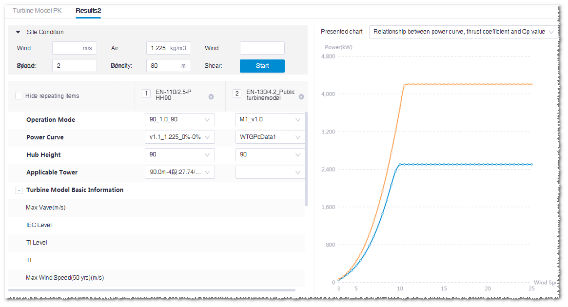
Results
The Results page shows the comparison of turbine model parameters, economy, and engineering quantity among different turbine models or a turbine model in different conditions (such as in different operation modes).
Note
The number of selected turbine models is displayed at the right side of the Results tab.
To check the PK results, perform the following steps:
- Input the site condition, including wind speed, air density, wind shear, k value, and wind height.
- Select the operation mode, power curve, hub height, and applicable tower of each turbine model. These parameters are acquired from the turbine model series to which the turbine model belongs.
- (Optional) Click the delete icon at the right side of the turbine configuration name to delete it from the result table.
- Click the Start button. The basic information, power production economy, and engineering quantity are displayed in the table. At the right side of the interface, the power curve of each turbine model is displayed. The curve type consists of relationship between power curve, thrust coefficient and Cp value, power performance rendering, comparison chart of power generation performance at a specific K value, and normalized power curve.
Turbine Version Broadcasts
This help users quickly know about the current latest turbine series and related information. At the same time, it provides version reminders during the process of turbine series usage, power production evaluation, and version release.
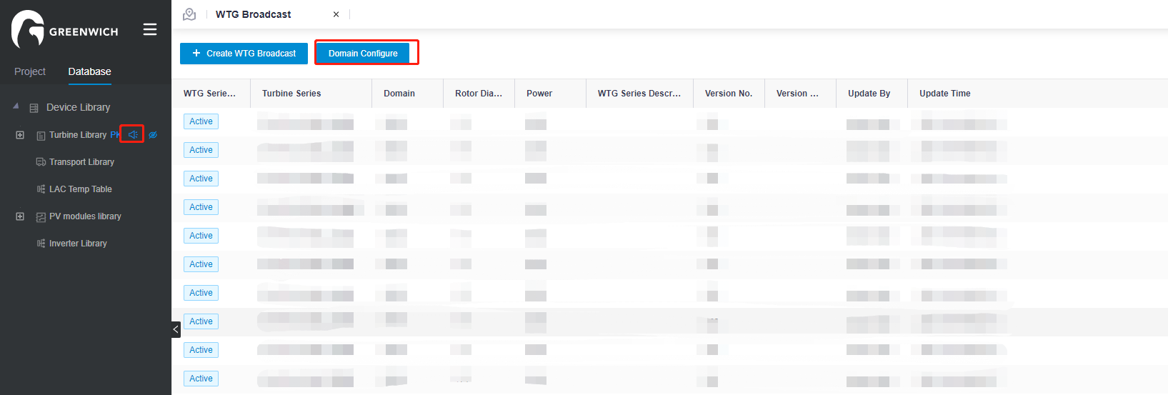
Manage Turbine Version broadcasts
Administrators can manage Turbine Version broadcasts through the following operations.
Configure a domain
All broadcast turbine series must exist in a managed domain.
Double-click the small speaker icon next to Turbine Library to enter the WTG Broadcast management panel, click Domain Configure, and then select the required managed domain.
Manage from the WTG Broadcast panel
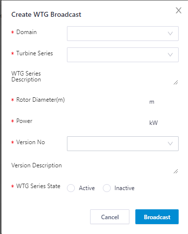
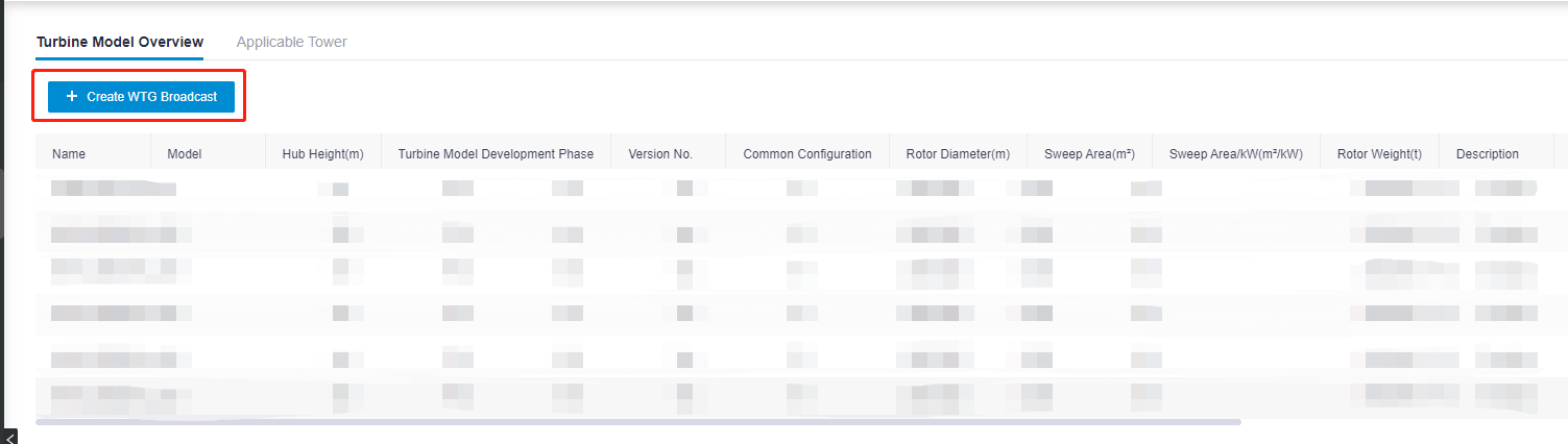
In the WTG Broadcast panel, click Create WTG Broadcast to set parameters, and then click Broadcast to broadcast the turbine information.
Manage from the Turbine Series panel
If the domain has been set in Domain Configure, you can directly broadcast turbine series in the Turbine Series panel under the domain.
Double-click Turbine Series to open the panel, click Create WTG Broadcast to set parameters, and then click Broadcast to broadcast the turbine information.
Cancel Turbine Version broadcasts
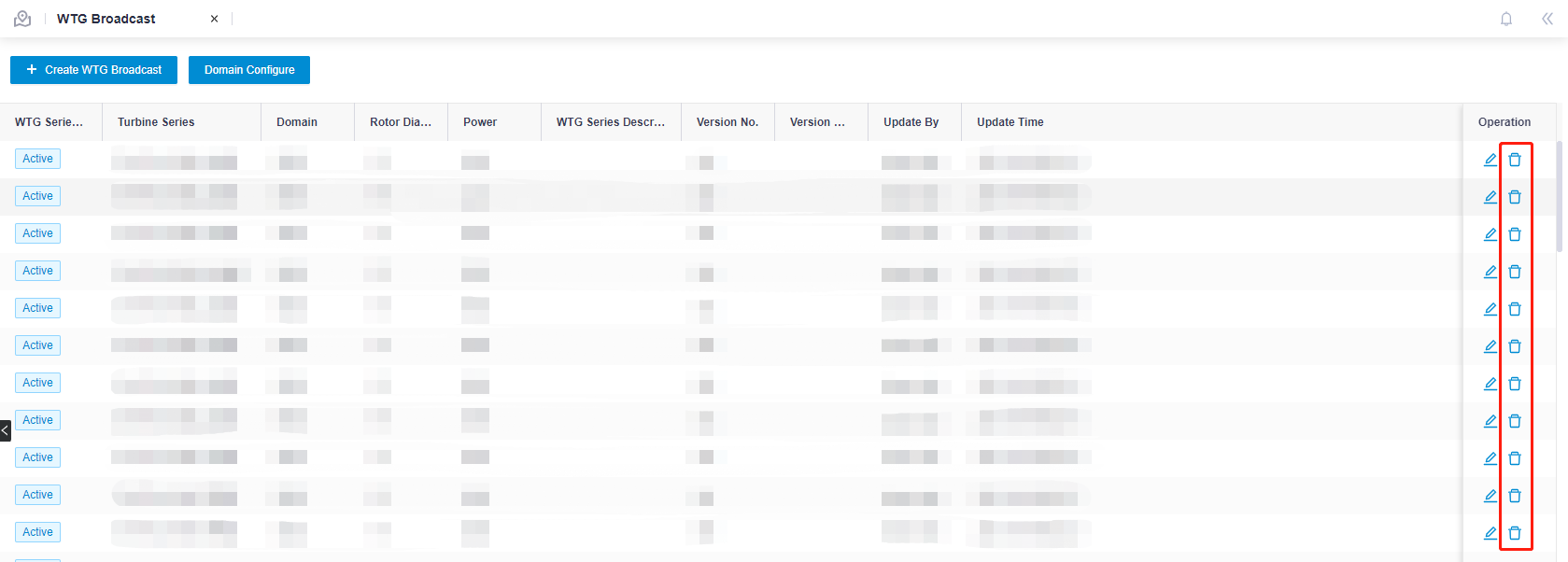
To cancel a WTG broadcast, administrators can click the Delete button in the WTG Broadcast panel.
Check Turbine Version broadcasts
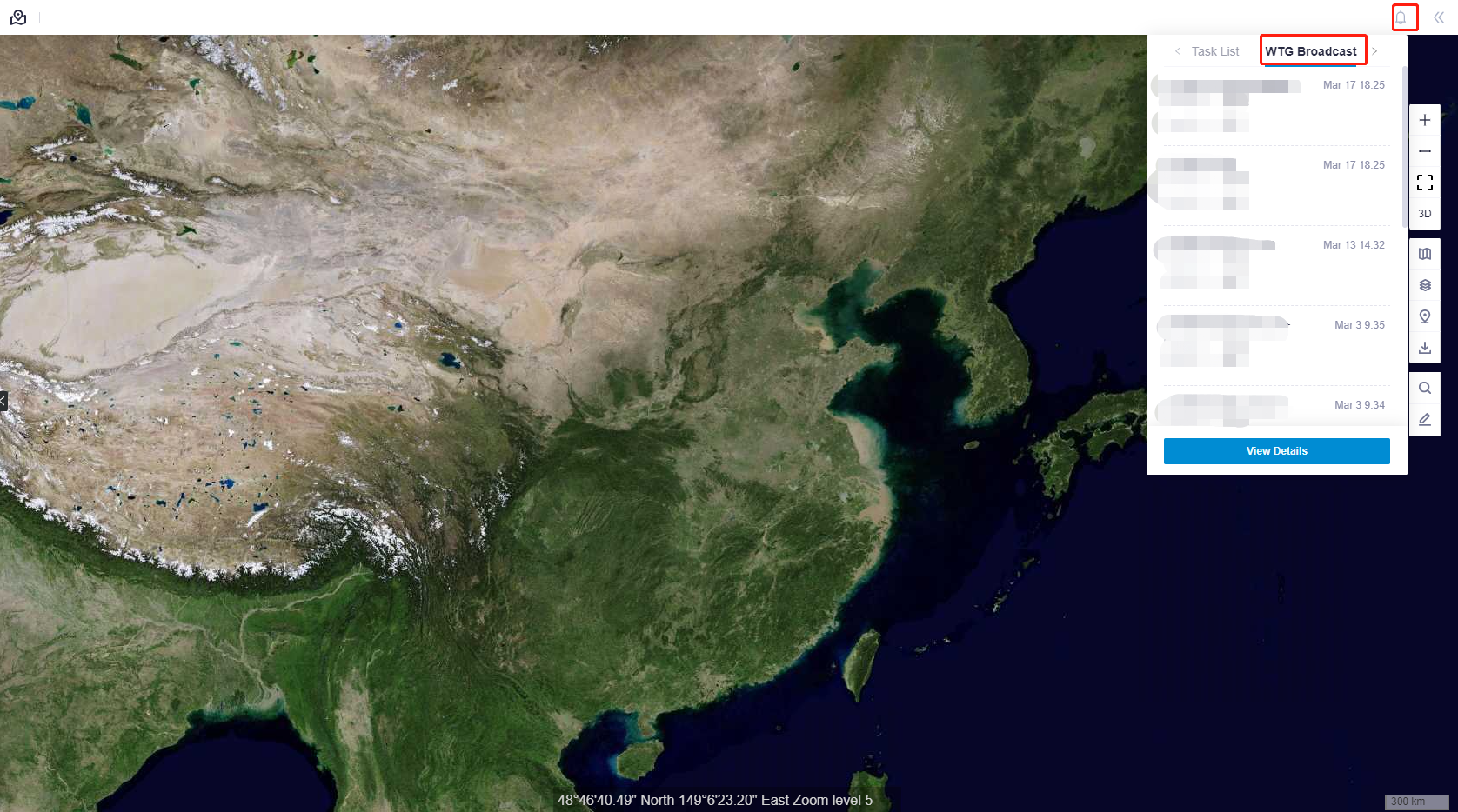
Check from the WTG Broadcast panel
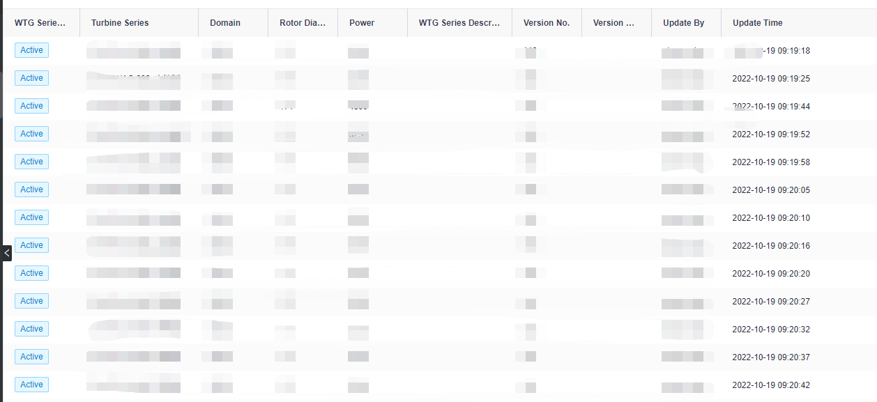
Double-click the small speaker icon next to Turbine Library to enter the WTG Broadcast panel. Then, you can check Turbine version broadcasts.
Check from the system notification icon
You can see the recent turbine broadcasts by clicking the system notification (small bell) icon. Click View Details to go to the WTG Broadcast details panel.
Transport Library
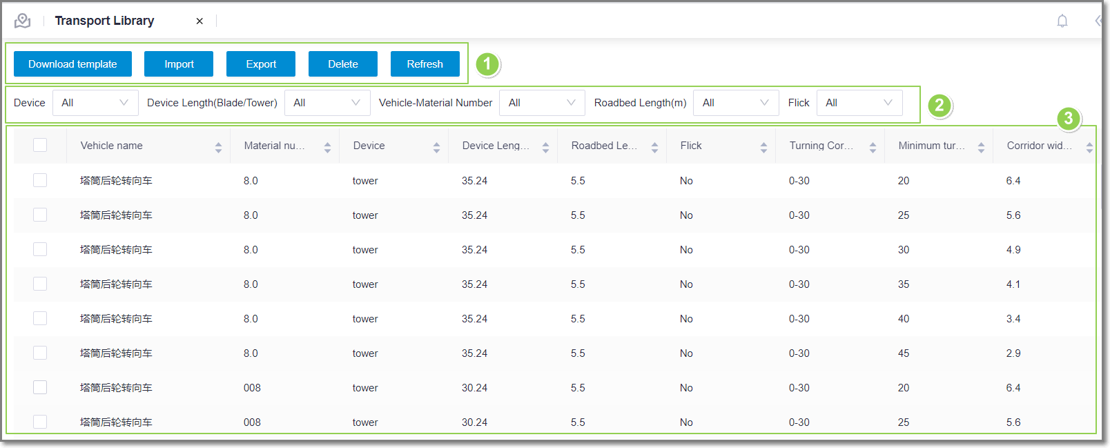
Transport library demonstrates the parameters configured for turbine components transportation. These parameters are references for route design, and are updated regularly by the Greenwich staff.
The interface of transport library is shown as in the following figure:
Figure: Transport Library Interface Overview
| No. | Name | Description |
|---|---|---|
| ① | Operation buttons | Display the operation buttons for transport library. Their usages are show as below:
|
| ② | Filters | Select the options in the Device, Device Length, Vehicle-Material Number, Roadbed Length, and Flick drop-down menus to filter the items displayed in the table. Each time you select a filter, the data table is refreshed automatically. |
| ③ | Transport data table | Display the bend parameters in different conditions of transport device, vehicle, roadbed and so on. |
PV Module and Inverter Library
PV module and inverter library contains the parameters of mainstream pv modules and inverters type. The parameters are references for project.
PV Module View:
Expand the supplier name to view the pv modules of this supplier. Only administrators are allowed to add, edit and delete pv modules.
- Click database>device library>pv module library.
- Double click the component name. The overview page displays the component details
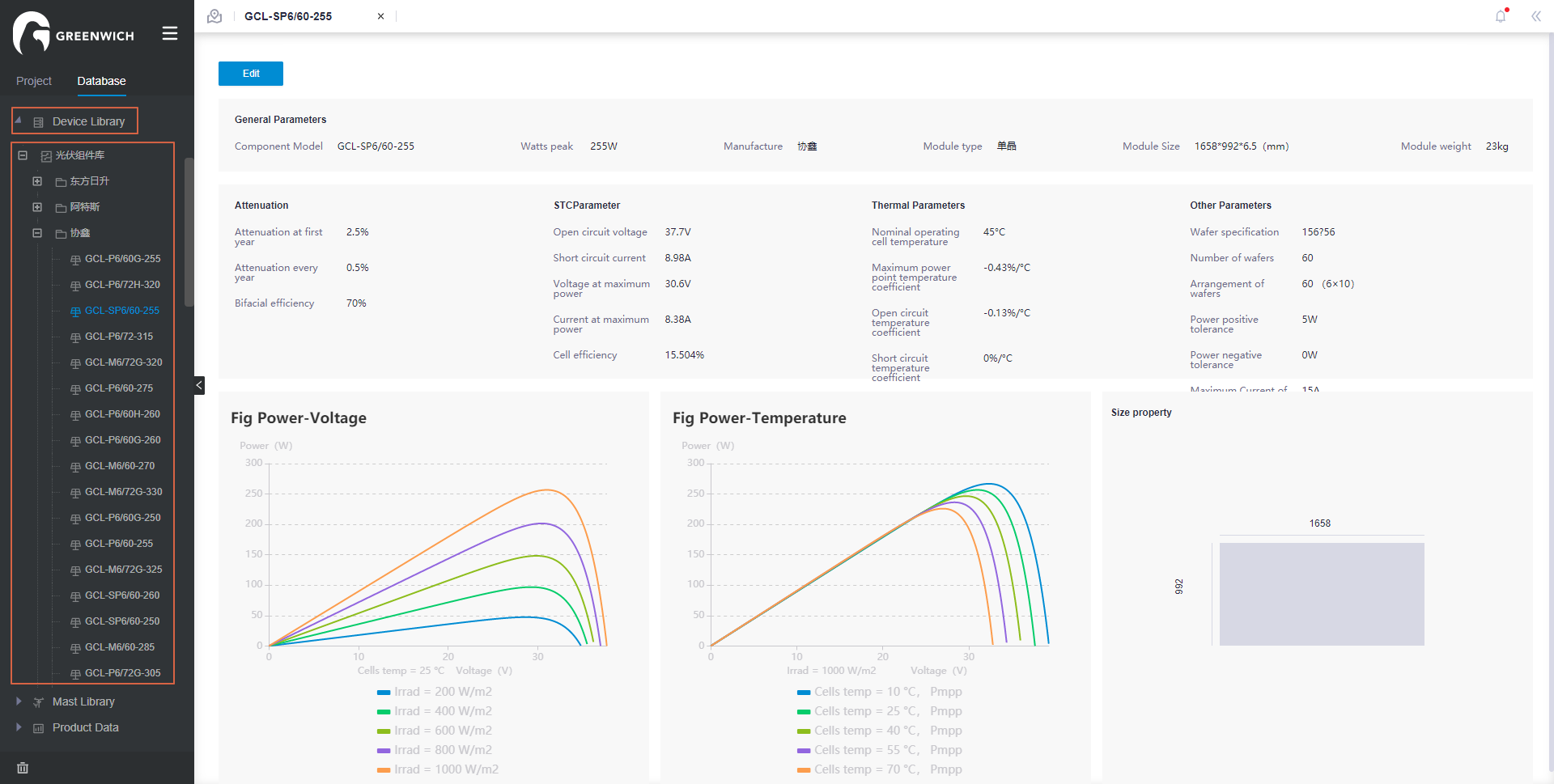
The module property includes general property, attenuation, STC Parameter, temperature parameter, other parameters. The below fig power-voltage, fig power-temperature, size property diagrams are based on module property.
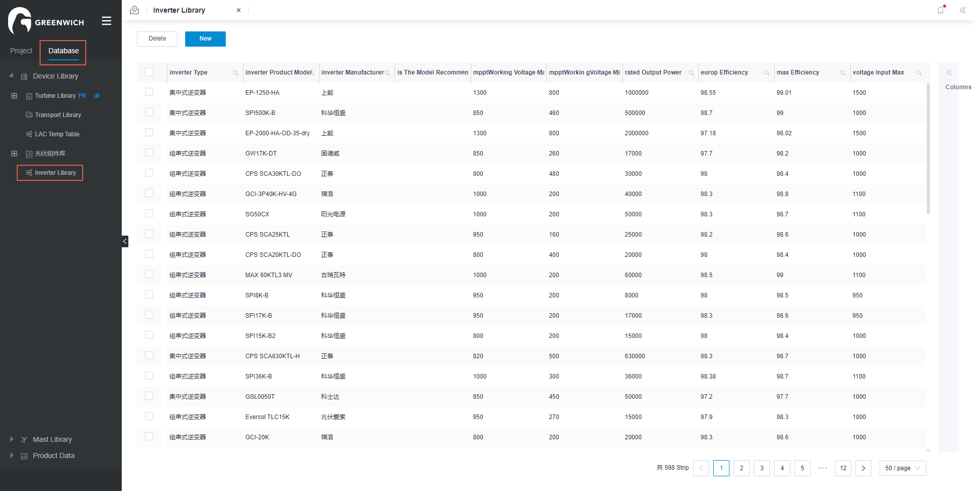
PV inverter view:
Only administrators are allowed to add, edit and delete pv inverters.
Click database>device library>inverter library.
Product Data
The Product Data module provides essential data basis for optimization design, engineering quantity and cost generation of entity modules in Greenwich. This module is comprised of material library, PBOM template, model library, unit price library, and cost estimation template.
Each sub-module in the Product Data module is maintained by professional data administrator of Greenwich. So this section provides only a brief introduction on the functions of each sub-module.
Material Library
Material library includes the facility and project service materials and material groups used in the wind farm project. Each material or material group is assigned with a specific number for recognition in the project design.
The hierarchy in the material library is consisted of four levels, and the materials are embedded in the fourth level. Operations in each level of hierarchy are listed as below:
- Double-click the item in the first or second level to check and edit its substructure.
- Double-click the item in the third level to open the material group details page. On this page, check the material group details, add material group, and import material group(s).
- Double-click the item in the fourth level to open the parameters page of material. On this page, check the material details, add material, import/export material, and enable/disable the material.
The material library administrator maintains the material data in this module.
PBOM Template
PBOM template provides the bill of materials needed in the wind farm life circle design, engineering, purchasing, and cost assessment process, and all material groups composing this bill. In this template library, all the templates are categorized as ten project unit, including route, platform, foundation, turbine and tower, substation, WTG transformer, other projects in wind farms, mast and outgoing line. Four levels comprises a project unit structure.
- Double-click the first three levels to check and edit its substructure.
- Double-click the fourth level template to open the PBOM detail page. Check the material groups included in this template.
The PBOM template administrator maintains data in this module.
Model Library
Model library collects the PBOM models used in some specific project design scenarios. Its structure is the same as the PBOM Template module.
- Double-click the first three levels to check and edit its substructure.
- Double-click the fourth level template to open the model detail page. Check the models applied in the specific project, and edit, add, enable/disable these model.
Unit Price Library
Unit price library collects the material price with various properties in the specific quarter. By defining the filters, you are enabled to search for your desired material price with efficiency and accuracy.
The unit price library administrator is responsible for importing price, freezing invalid price, checking log file, and updating recommended algorithms of unit price library.
Cost Estimation Template
The cost estimation template module embodies engineering quantity template of professional facilities and materials used in feasibility study, cost estimation template in feasibility study, and engineering quantity template of unit project.
The model administrator configures the mapping relationships and calculation rules between various templates and PBOM templates.