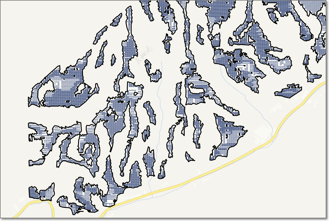
PV Layout Optimization
Import PV Module
The user can create or import pv module into the project.
Create pv module
a)Click the project name.
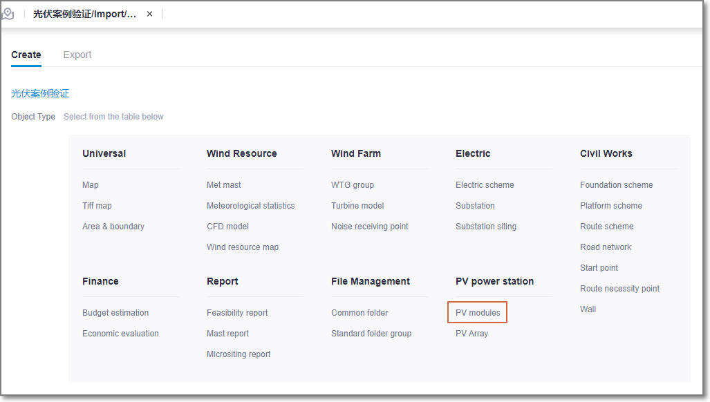
b)Click the import/export in the operation button menu at the left bottom of the interface. Click the Create tab, select the category as pv module.
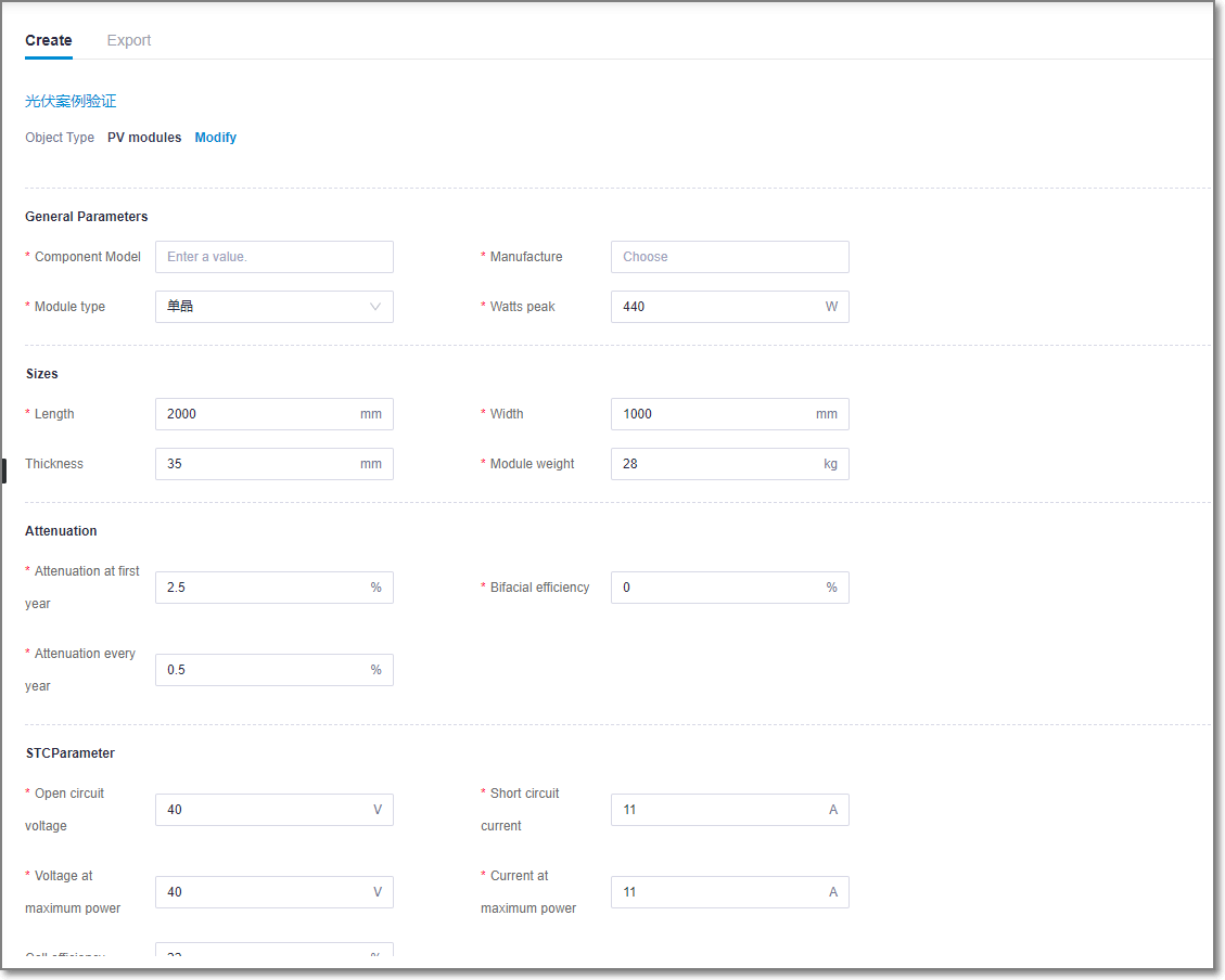
c)Fill in each item then click Create to complete the PV module creation.
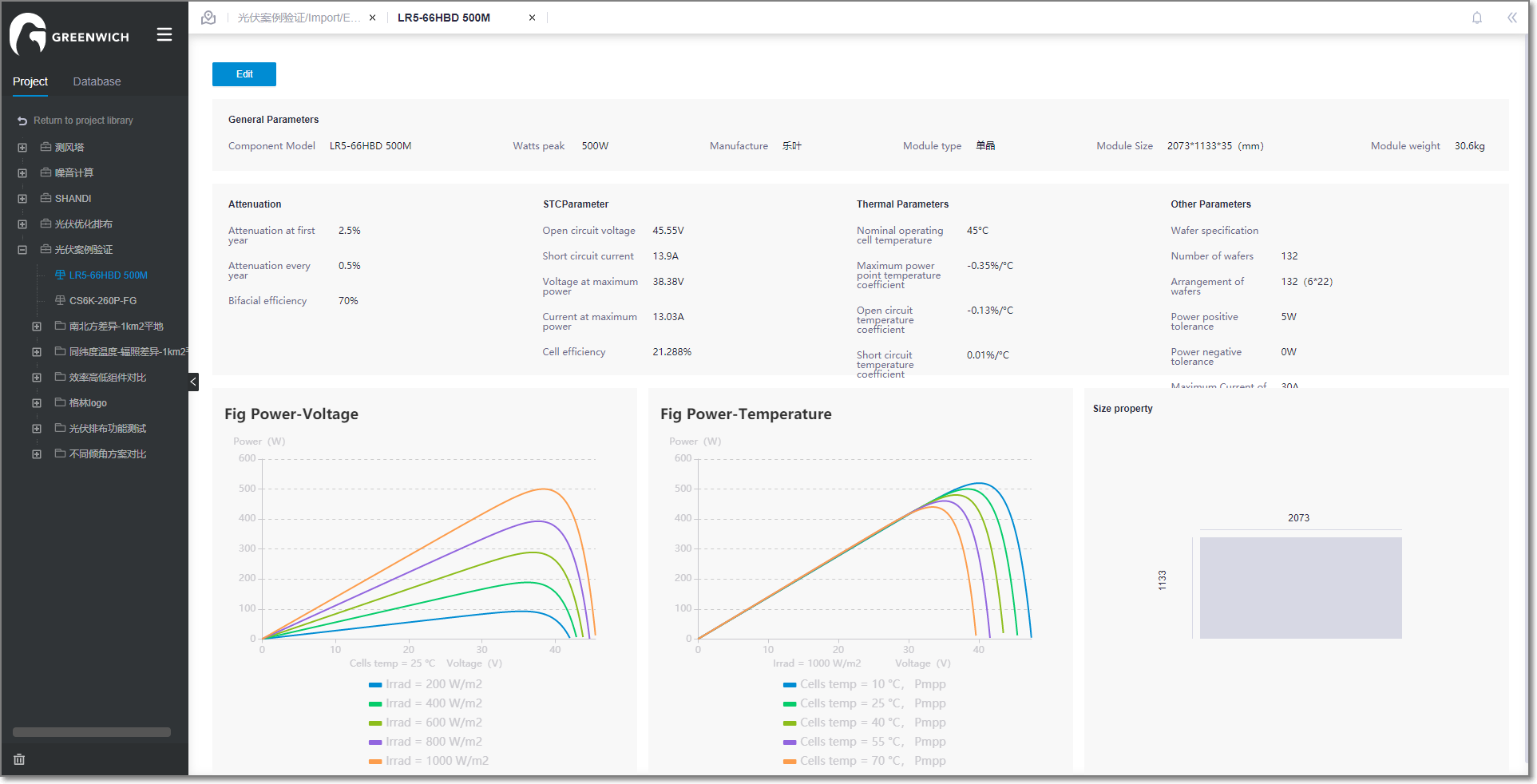
PV module info includes general property, size, attenuation, STC Parameter, temperature parameter, other parameter. PV module parameters can be inquired and downloaded from the official website of the pv module manufacturer.
d)Double-click the new module name to display details.
Import pv module
Select the project, then click the import button on the bottom of the page. Select pv components to create a copy of a component under the project.
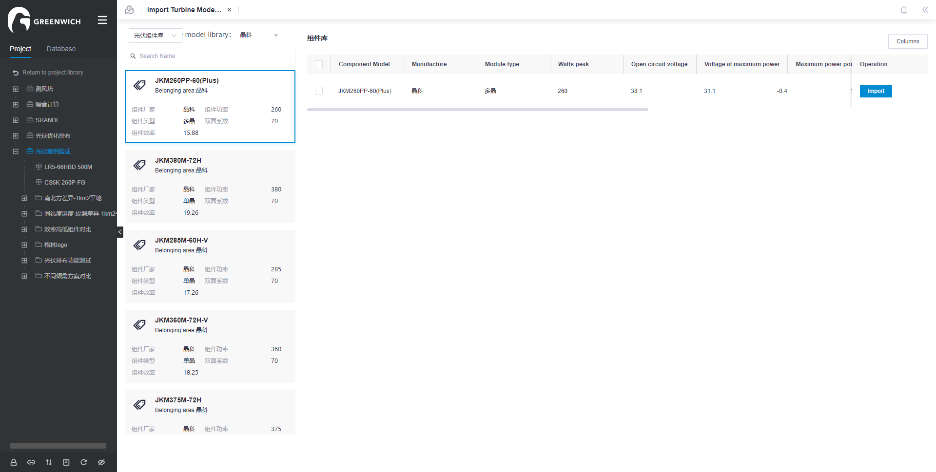
Create PV Array Scheme
If operating on the existing pv arrangement scheme, the previous design results will be overwritten.
Click the project name or the layout folder in the project pane.
Click the Import/Export icon
 in the operation buttons area at left bottom of project pane to open the Import/Export page.
In the Create tab, select PV Array from the menu.
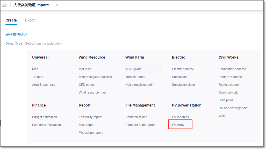
Click the Create radio button.
Configuring PV Array Property
Before layout optimization, ensure there are region file and map file under the project. Map file refers to Map . Region file refers to Macrositing .
Click the PV array object in the project pane.
Click the expand icon《 to open the operation pane.
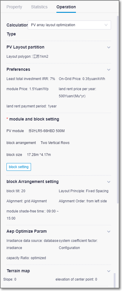
Select PV array layout optimization from the Calculation Type drop-down menu.
Click the expand icon
 in the PV Layout partition and select the scope.
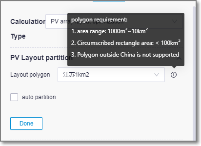
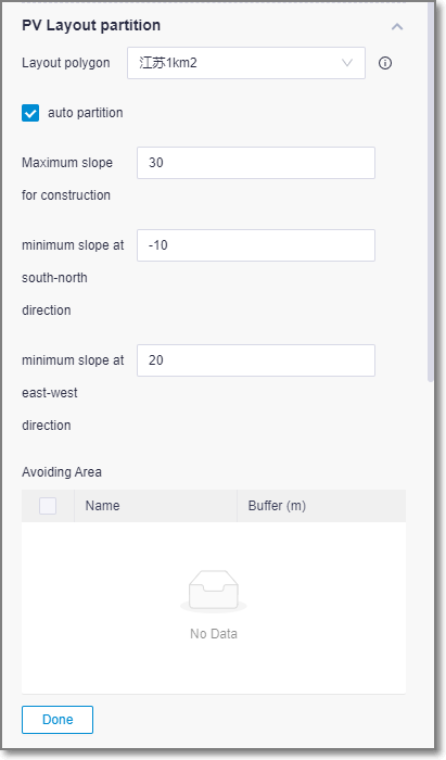
Parameter/Option Description Layout polygon pv array areas. According to the general scale of centralized photovoltaic power station, the area is required to be 1000m2~10km2, and the outer rectangle (the range enclosed by the maximum and minimum longitude and latitude) is less than 100km2. Auto partition Within a given site, there are some areas that are not available due to shaded topography and need to be further divided into small ranges, known as partitions. User can choose existing partition files or let the system partition automatically on request. Maximum slope for construction The cost of installing photovoltaic brackets is too high in large slope areas. To avoid layout in such areas, the maximum slope allowed for construction should be set, which is generally recommended to be 30 degrees. Minimum slope at south-north direction If the slope of the north-south slope is too small (negative in the north and positive in the south), the array spacing will be too far and the project cost will be too high. Set the minimum north-south slope to avoid such areas. The recommended value is -10 degrees. Maximum slope at east-west direction For east-west terrain, if the slope is too high, the array will not be irradiated effectively in the morning or afternoon. Set the maximum east-west slope To avoid such areas. The recommended value is 20 degrees. Click the expand icon
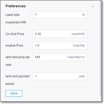
 in the Preferences and configure the main parameters for the array optimization layout.
Click block setting on the module and block setting. Select modules and inverters.
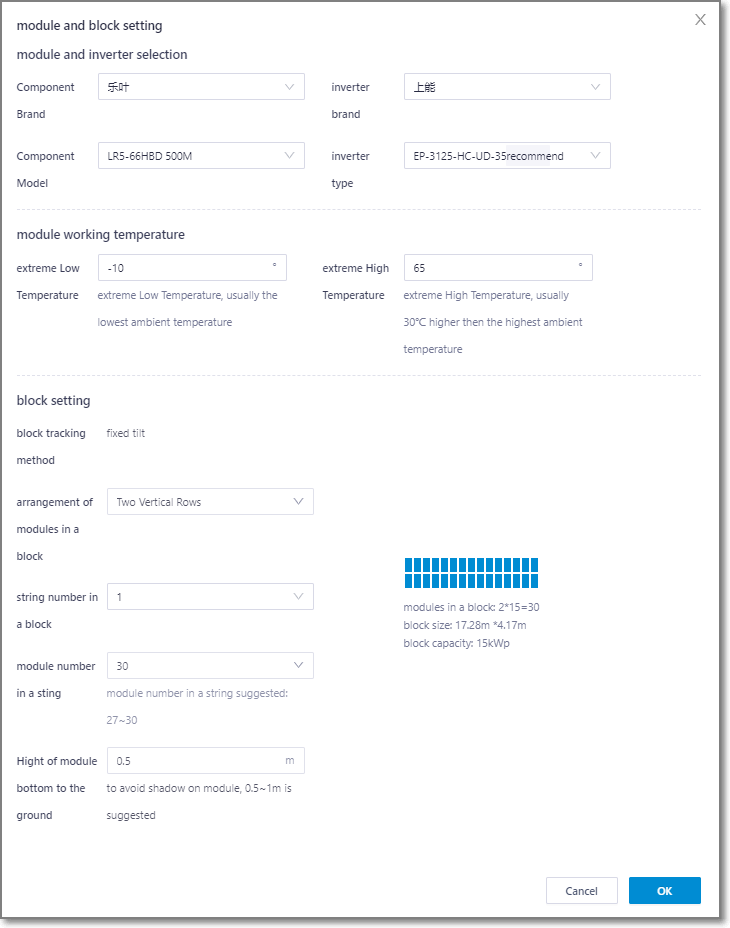
Click the expand icon
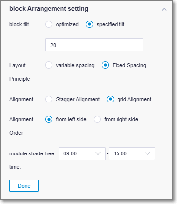
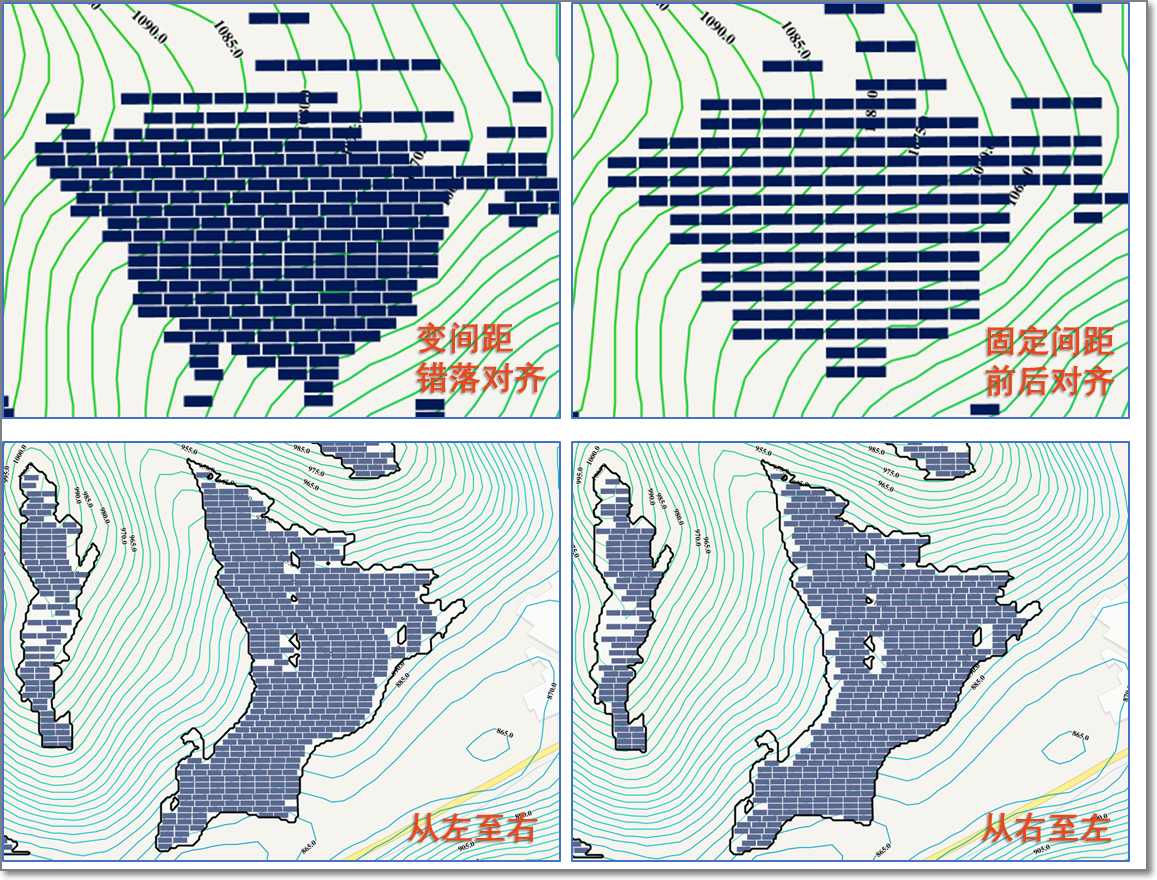
 in block arrangement setting,select array tilt, array arrangement, alignment, alignment order, module shade-free time then click done.
Click the expand icon
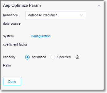
 in AEP Optimize Parameter to configure system coefficient factor and capacity ratio.
Click the expand icon
 in terrain map to configure terrain. User can choose terrain of the project or customized terrain. The customized map is for flat, water surface, slop.
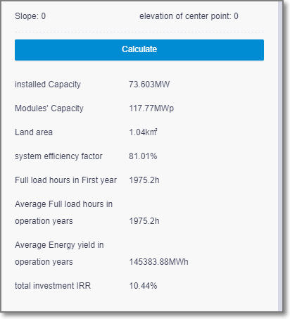
Click Calculate. The task is submitted successfully.
Checking Calculation Task
Choose Tools Library > Task List and select PV array from the drop-down menu. When the task progress reaches 100%, the calculation is completed.

Checking Calculation Result
Check the AEP-related results at the bottom of the operation pane.
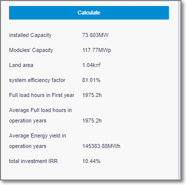
Double-click the pv array scheme name on the left domain tree to view the details.
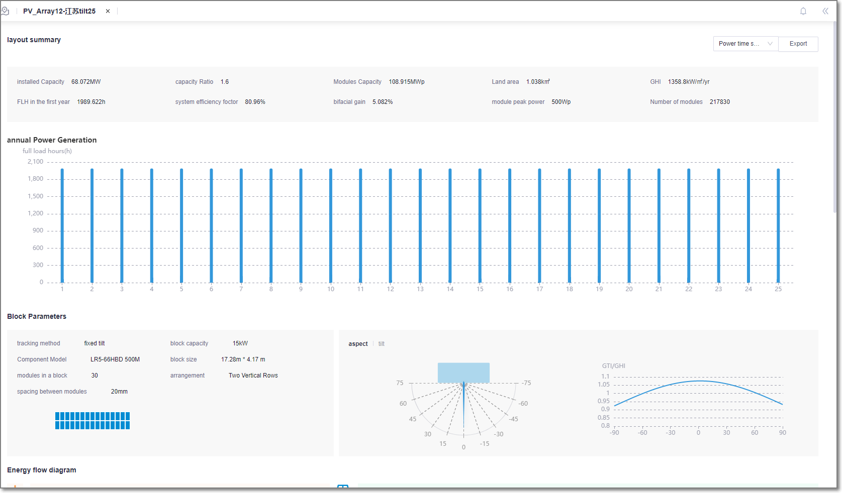
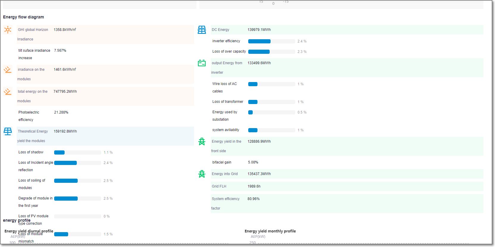
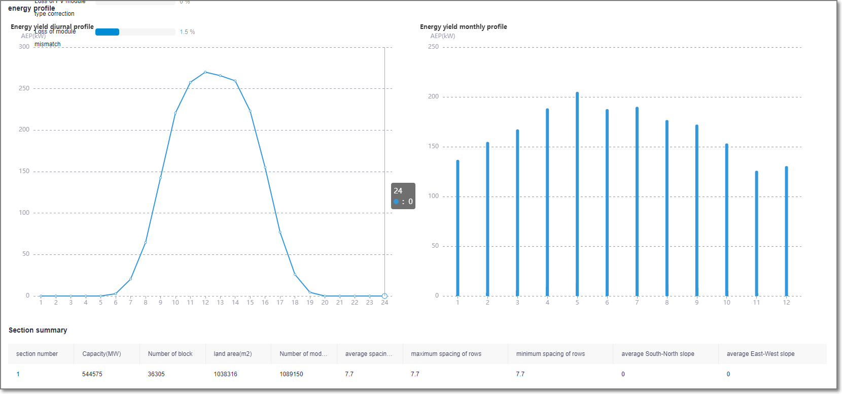
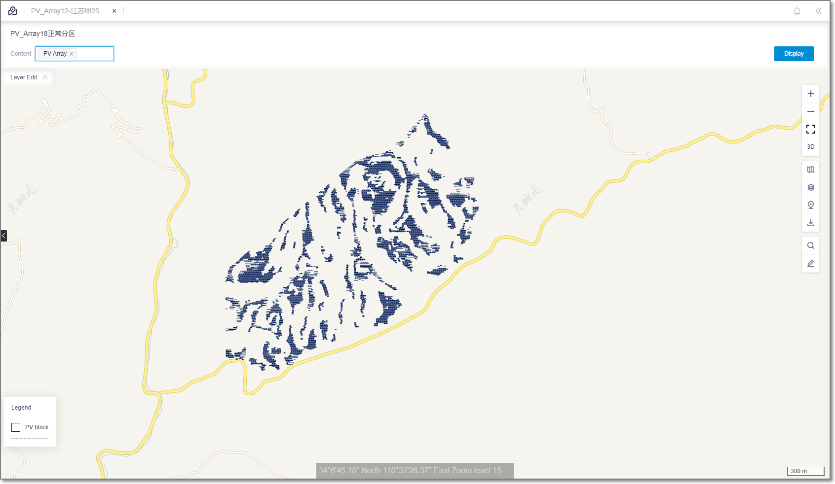
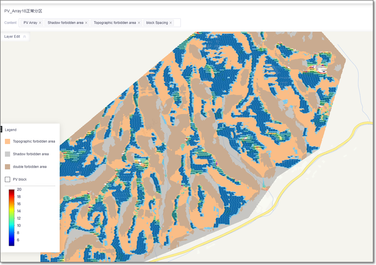
Select the pv array scheme and open the GIS do display pv layout. Open layer edit to view shadow, terrain and block.
Export Partition Polygon
If the user selects automatic partition, the partition range will be generated and can be exported according to the site range, which can be used as the reference for the project land acquisition
