Macrositing Pro
Macrositing Pro is a refined macrositing approach to recommend locations of wind farm, turbine, and mast within defined wind farm boundary, and calculate wind farm construction cost, with regard to regulations of minimum full-load hours per WTG and avoid areas.
Selecting a Wind Farm Boundary
The first step of macrositing is to select a scope. Two methods are available: importing a wind farm boundary and drawing a wind farm boundary manually.
Importing a Wind Farm Boundary
- Select a project name in the project pane.
- Click the Import/Export button
 in the operation button area.
 - On the Create page, select Area & boundary in the menu.
- Select Wind Farm Boundary in the Polygon Category drop-down menu.
- Click the Upload button to import the wind farm boundary file. The format is txt, kml, or kmz. The wind farm boundary file can be acquired from the following two approaches:
- Download the boundaries in GIS. Learn more in the section Data Download.
- Click the Download Template button to download the template file in the txt format, and input coordinate of inflection point of the polygon.
- Select projection, zone, and datum.
- Input the name of polygon.
- Click the Create button. The newly created polygon appears in the project pane.
Drawing a Wind Farm Boundary
- Draw a polygon in GIS. Refer to the section Drawing a Polygon for more details.
- Save the polygon as Wind Farm Boundary. The newly created polygon appears in the project pane.
Performing Macrositing
According to customer requirements and wind farm condition, perform macrositng and calculate the cost and benefit of wind farm.
Click the wind farm boundary object in the project pane.
Click the expand icon 《 to open the operation pane.
Click the Operation tab.
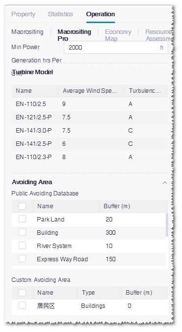
Click the Macrositing Pro tab.

Input the value of minimum power generation hours per WTG.
Select avoid area.
a.Select avoid areas in the Public Avoiding Database list from the Greenwich public database. The database consists of building, height district area, river system, etc.
b.Select areas in the Custom Avoiding Area list. The options in the list are polygons in the project that are saved as protection areas, farmland, existing wind farms, etc. Refer to the section Drawing a Polygon for more information.
In the Turbine Model area, four widely-used envision turbine model series are recommended and their performance parameters are displayed. They are not editable. If you want to select some specific turbine models, perform micrositing with reference to the section Planning and Siting.
Note
After the calculation, the common turbine models embedded in the turbine model series are automatically imported into the project. If a turbine model at the same hub height already exists in the project, by default, this turbine model in the project is used in the calculation.
Click Calculate. When the calculation is completed, the result is displayed in the lower area of operation pane, including total capacity, annual on-grid power, annual equivalent full-load hours, total No. of turbines, mean wind speed at turbine location, and LCOE.
Checking Macrositing Result
After macrositing, check the turbine layout, and location, wind resource, and cost of each turbine location.
After macrositing Pro, a layout folder named as <wind farm boundary name>-WindFarmLayout is generated in the project pane.
- Click the check box before one or some of the turbine locations. The turbine layout, wind resource grid, or map is displayed in GIS. Refer to the section Checking Macrositing Result for more details.
- Double-click the layout result sub-folder. The turbine layout overview page opens. Check the location, wind resource, and other parameters of each recommended turbine location.
- Expand the Column Settings pane at the right side and select LCOE, CostRoad, and CostElectLine. These three parameters are results from macrositing Pro.