CFD Model
This section introduces how the CFD model is built based on wind farm circumstances, terrain, landform, and weather characteristics to obtain CFD wind speed and turbulent kinetic energy (CFD Rans) around target wind farm area. The CFD rans result and collected mast data will be post-processed (Syntheses CFD Calculation) to generate wind resource map of the target wind farm.
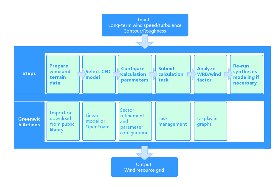
The process of CFD model establishment is shown in the following figure:
Figure: CFD Modeling Process
Building up CFD Model
Before CFD model simulation, create a CFD model object in the project.
- Click the project name in the project pane.
- Click the Import/Export icon in the operation buttons area to open the Import/Export page.
- Select CFD model from the Object Type menu.
- Click the Done button. A CFD model object is created in the project pane named CFDModel1.
- Click the CFD model object in the project pane, and click the expand icon 《 to open the operation pane.
- Click the Property tab, click the name to make it editable, and change the name.
- Click the Save button to save the changes.
CFD Replication Function across Projects
Select the reference project and click the Import/Export button
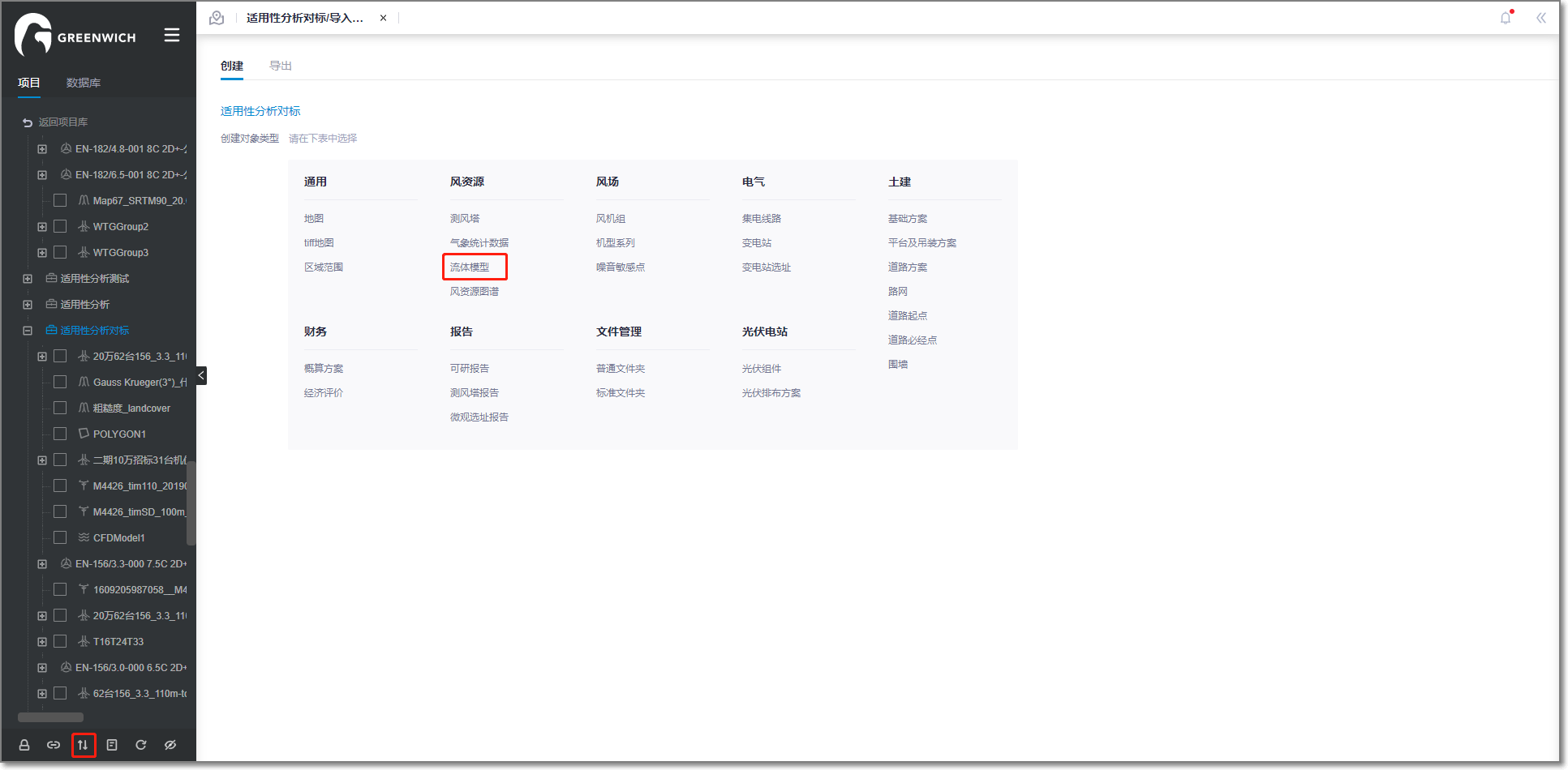
Select fluid model
Select online import
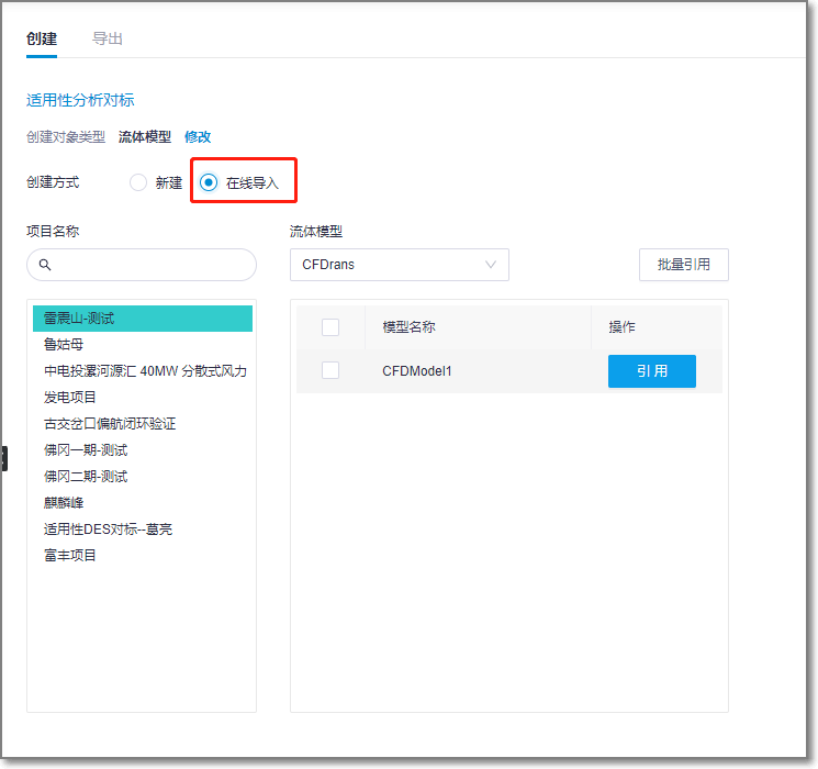
All projects locked by users will be displayed on lower left corner. The user can also search the projects that need to reference CFD model through the search box in the upper left corner.
There are RANS and DES models under fluid model.
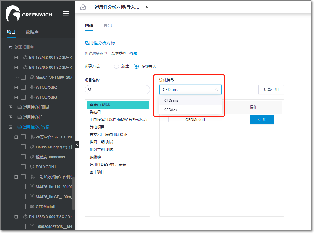
Select the reference CFD model object and click confirm.
Note
Multiple object references across CFD model types are not supported.
The referenced fluid model under the project will be displayed once the reference process is complete.
CFDRans
Before creating a CFD model object, ensure the mast, map, and wind farm boundary objects are already added in the project. The map and wind farm boundary should be defined with coordinate.
For details of map file, refer to the section Map.
For details about wind farm boundary, refer to the section Macrositing.
Check the format of the wind farm boundary file from the template and edit it if necessary. The other way is to draw a polygon and save it as WindRange. Refer to the section Drawing a Polygon for more details.
Click the CFD model object in the project pane
Click the expand icon 《 to open the operation pane.
Click the Operation tab. Select Sector-wise as CFD calculation type.
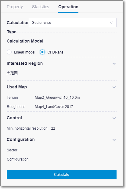
Select the CFD model as Linear model or CFDRans.
- Linear model: Applied in projects in flat areas.
- CFDRans: Applied in projects in hilly areas.
Click the expand icon
 in the Interested Region section to show the regions.
All the polygons and regions saved in the project are listed in the list. In the calculation, the rectangle outside the map are expanded in all four directions.
Interested region is the target scope of wind farm planning. The selected interested region displays in GIS and glitters.
Click the OK button to save the changes.
Click the expand icon
 in the Map section to show the map settings.
Select a terrain map from the Terrain drop-down menu.
This is mandatory.
All the map files in the project and public map libraries are listed in the menu.
Select a roughness map file from the Roughness drop-down menu.
All the map files with roughness information in the project and public map libraries are listed in the menu.
Click the OK button to save the changes.
Click the expand icon
 in the Control section to set up Min. horizontal resolution.
Click the expand icon
 in the Configuration section to set up sectors and configuration.
Note
This section is available only for the CFDRans CFD model.
Input the No. of sectors in the Total Sector Number field. The 360 degrees of interest region are divided into sectors in the defined number starting from 0 degree at center longitude.
The number of sectors should be larger than 1, and default is 12.
Click the Sector Refinement button to open the corresponding window.
For each sector, select a number from 1 to 3 in the number of refinement drop-down menu. The sector is refined to minor sub-sectors.
Click the OK button to save the changes.
Select a configuration type in the Configuration drop-down menu.
It is recommended to select Default to use the default CFD configuration parameters.
Click the Generate List button in the operation pane. The details of configuration parameters are listed in the pop-up window.
After confirmation of the parameters, click OK to save the changes.
Click Calculate.
After the task is submitted, a message pops up: Task has been submitted. Please go to task list.
Choose Tools Library > Task List.
Select CFD (for linear model) or CFDRans in the task type menu to check the status.
Click this task, the calculation progress of each sector-wise is displayed in the table below.
Syntheses CFD Calculation
Click the CFD model object in the project pane, open the Operation pane.
Select Syntheses as CFD calculation type.
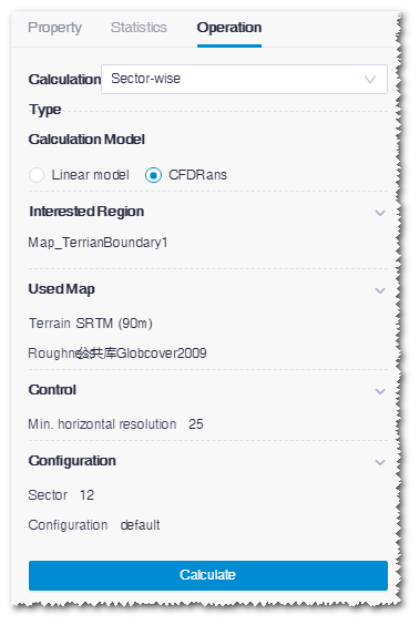
Click the expand icon
 in the Mast Data section, select mast(s), and set up the height and type.
All the mast objects saved in the project are listed in the list.
You can select more than one masts.
Note
If you select multiple masts, ensure they are of the same type.
The available types are: Wind Speed, Turbulence, and WindSpeed and Turbulence. The mast in the tab format can only be defined as the type of wind speed.
Click the OK button to save the changes.
Click the expand icon
 in the Control section to set up Hub Height and Air Density.
- Hub height: Hub height of target turbine
- Air density: Air density at the specified sea level. The data source is mast data. a.s.l:at sea level
Click the OK button to save the changes.
Click Calculate.
After the task is submitted, a message pops up: Task has been submitted. Please go to task list.
Choose Tools Library > Task List.
Select Linear Model in the task type menu to check the status.
Checking Results
Before checking the results, ensure the calculation task is successfully submitted and calculation is completed.
Checking Calculation Result of CFDRans
Select the CFD model object in the project pane.
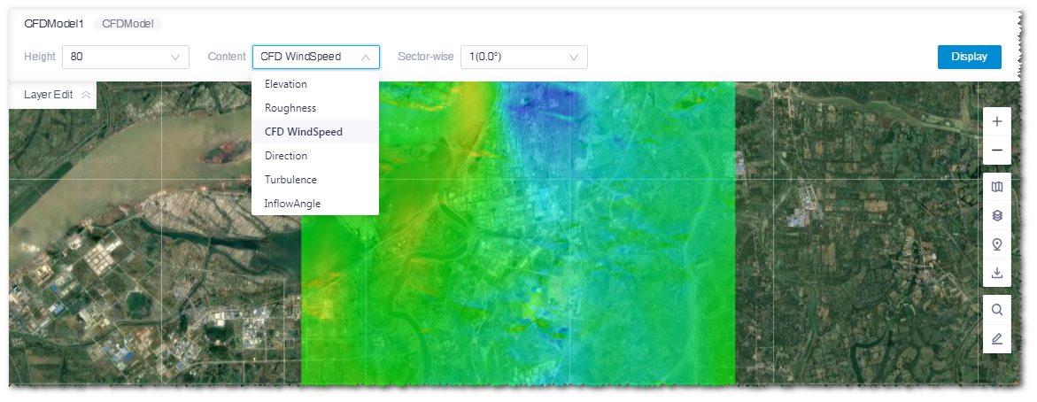
Expand the Layer Edit panel at the left top of GIS.
Select the height, content, and sector-wise to check the wind speed factor, turbulence intensity, and other content at each height in the CFD model.
| Name | Description |
|---|---|
| Height | The height of calculation result. The seven heights saved in Greenwich are 30/50/70/80/90/100/140. |
| Content | Elevation: Terrain information of the project. Roughness: Roughness distribution of the project. CFD WindSpeed: Distribution of wind speed in CFD calculation result. The wind speed displayed here is result from the CFD calculation, not the real wind speed. Direction: Horizontal wind direction from the CFD calculation result. Turbulence: Turbulence intensity from the CFD calculation result. The turbulence intensity displayed here is calculated from TKE and speed in CFD, not the real turbulence intensity. |
| Sector-wise | Sector information from the CFD result. |
Checking Syntheses Calculation Result
After CFD model calculation with linear model, the corresponding wind resource map object is generated in the project.
Click the refresh icon
 in the operation button area. The newly generated wind resource map appears in the project pane.
Click the check box before the wind resource map object and expand the Layer Edit > ResourceGrid panel.
Select the height, content, and sector.
Wind Resource Map¶ Name Description Height Height of the wind resource map. The default value is the hub height. To add height here, input more heights in the Control section of the CFD model calculation configuration pane. Content The following options are available in the content menu: Terrain height: Terrain information of the project. Wind speed: The predicted wind speed generated by Greenwich. It is the real wind speed. Weibull A: A in the Weibull distribution. Weibull K: K in the Weibull distribution. WPD: wind power density. Turbulence intensity: Real turbulence intensity after syntheses. Inflow angle: the wind speed angle in CFD result. Roughness Air density Wind shear Slope Sector Results displayed by sector. Click the Display button to show the selected contents in GIS. The wind resource map can be exported by clicking the Import/Export icon in the peration button area.
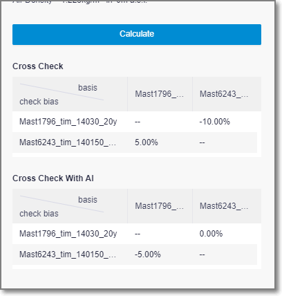
Cross-Checking
To make cross-checking available, the following conditions should be met:
- Select CFD model as linear model, or select Syntheses as calculation type.
- Select more than two masts in the same type in the mast sensor section.
- The CFD model calculation task is done.
The cross-test results include the error of the traditional CFD model and the error of the AI modified model.
